In the circuit shown in Fig the sources have emf'sξ1=1.0V and ξ2=2.5V and teh resistances have the values R1=10Ω and R_(2) = 20 Omega. The internal resistances of the sources are neglibile . Find a potential differences φA−φB between the plates A and B of the capacitance C.

As the capacitor is fully charged, no current flows though it, So current
i=ξ2−ξ1R1+R2(asξ2>ξ1)
And hence, φA−φB=ξ1−ξ2+iR2
=ξ1−ξ2+ξ2−ξ1R1+R2R2
=(ξ1−ξ2)R1R1+R2=0.5V

Topper's Solved these Questions
- ELECTRODYNAMICSBOOK - IE IRODOV, LA SENA & SS KROTOVCHAPTER - ELECTRODYNAMICSEXERCISE - Constant Magnetic Fiels - Magnetics
69 Videos
- ELECTRODYNAMICSBOOK - IE IRODOV, LA SENA & SS KROTOVCHAPTER - ELECTRODYNAMICSEXERCISE - Electromagnetic Induction
84 Videos
- ELECTRODYNAMICSBOOK - IE IRODOV, LA SENA & SS KROTOVCHAPTER - ELECTRODYNAMICSEXERCISE - Electric Capacitance - Energy Of An Electric Field
46 Videos
- ELECTRICITY AND MAGNETISMBOOK - IE IRODOV, LA SENA & SS KROTOVCHAPTER - ELECTRICITY AND MAGNETISMEXERCISE - All Questions
6 Videos
- ELECTROMAGNETISMBOOK - IE IRODOV, LA SENA & SS KROTOVCHAPTER - ELECTROMAGNETISMEXERCISE - All Questions
24 Videos
Similar Questions
In the circuit shown in Fig, the sources have emf'sξ1=1.5V,ξ2=2.0V,ξ3=2.5V , and the resistances are equal to R1=10Ω,R2=20Ω,R3=30Ω. The internal resistances of the sources are negligible. Find : ltbrtgt (a) the current flowing thorugh teh resistance R1 ,
(b) a potential differences φA−φB between the points A and B between the points A and B.

View SolutionIn the circuit shown in Fig. the emf of the sources is equal to ξ=5.0V and the resistances are equal to R1=4.0Ω and R2=6.0Ω. The internal resistance of the source equals R=1.10Ω. Find the currents flowing through the resistances R1 and R2.

View Solution
Knowledge Check
In the circuit shown in fig. the cell has emf 10V and internal resistance 1Ω
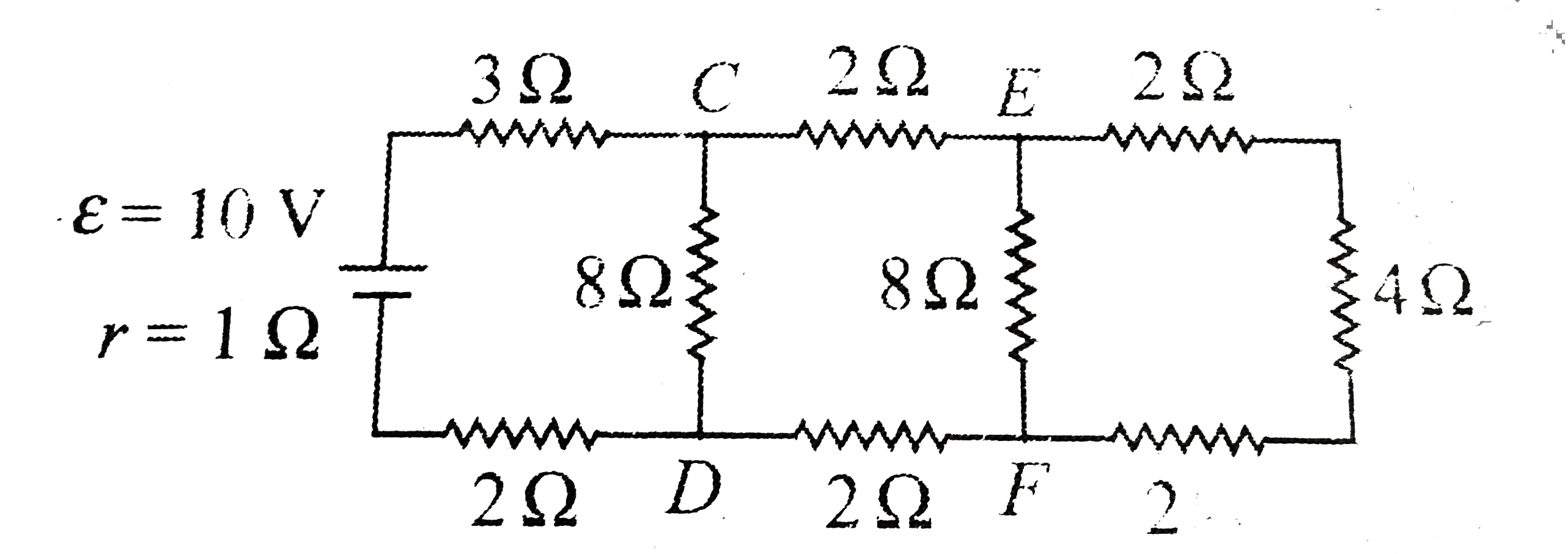 AThe current through the 3Ω resistor is 1A.BThe currents through the 3Ω resistor is 0.5 A.CThe currents through the 4Ω resistor is 0.5 ADThe current through the 4Ω resistor is 0.25 A.
In the circuit shown , the batteries have emf E1=E2=1V,E3=2.5V, and the resistance R1=10Ω,R2=20Ω, Capacitance C=10μF. The charge on the left plate of the charge on the left plate of the capacitor C at steady state is
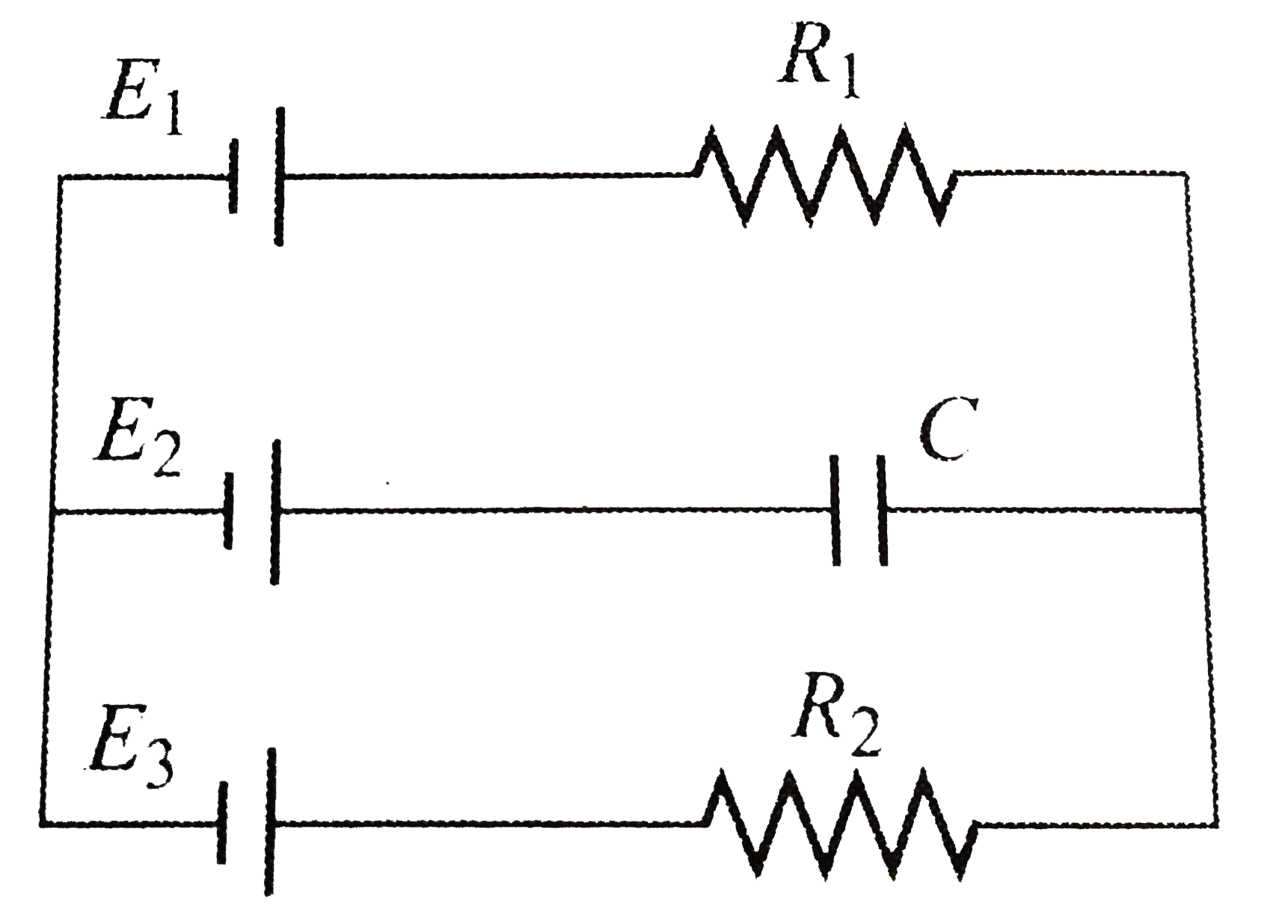 A+2μCB−4μCC−5μCD+12μC
In the circuit in figure emfE1=14V (internal resistance r1=1Ω),R1=6ΩR2=3.5Ω,emfE2=12v (internal resistance r2=0.5Ω),C1=4μF and C2=2μF.
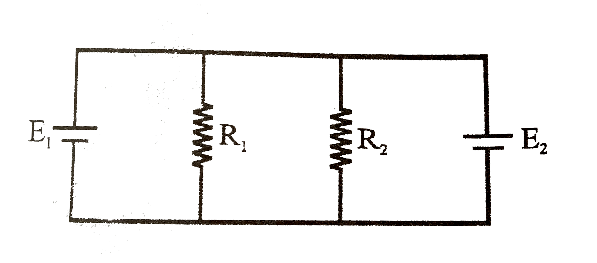
The potential difference across R1 isA2VB12VC14VD26V
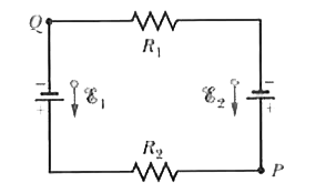
In Fig 27-56, the ideal batteries have emf emf12=200Vandε2=50V and the resistances are R1=3.0ΩandR2=2.0Ω. If the potential at P is 100 V, what is at at Q?
View SolutionFind a potential difference φA−φB between the plates of a capacitor C in the circuit shown in Fig, if the sources have emf'sE1=40V,E2=1.0V and the resistances are equal to R1=10Ω,R2=20Ω, and R3=30Ω. The internal resistances of the sources are negligble.

View SolutionFind the magnitude and direction of the current flowing through the resistance R in the circuit shown in Fig. if the emf's of the sources are equal to E1=1.5V and E2=3.7V and the resistances are equal to R1=10Ω,R2=20Ω,R=5.0Ω. The internal resistances of the sources are neglible.
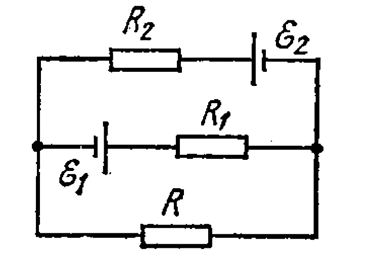
View SolutionIn the circuit shown in Fig. 4.68, the cells ε1 and ε2 have emf's of 4 V and 8 V and internal resistances of 0.5Ω and 1Ω respectively. Calculate the current in each resistance.
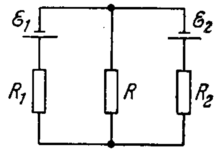
View SolutionIn a circuit shown in Fig, resistances R1 and R2 are known , as well as emf's ξ1 and ξ2. The internal resitances of the sources are negatible. At what value of the resitance R will teh thermal power generated in it be the highest ? What is it equal to ?
View Solution
