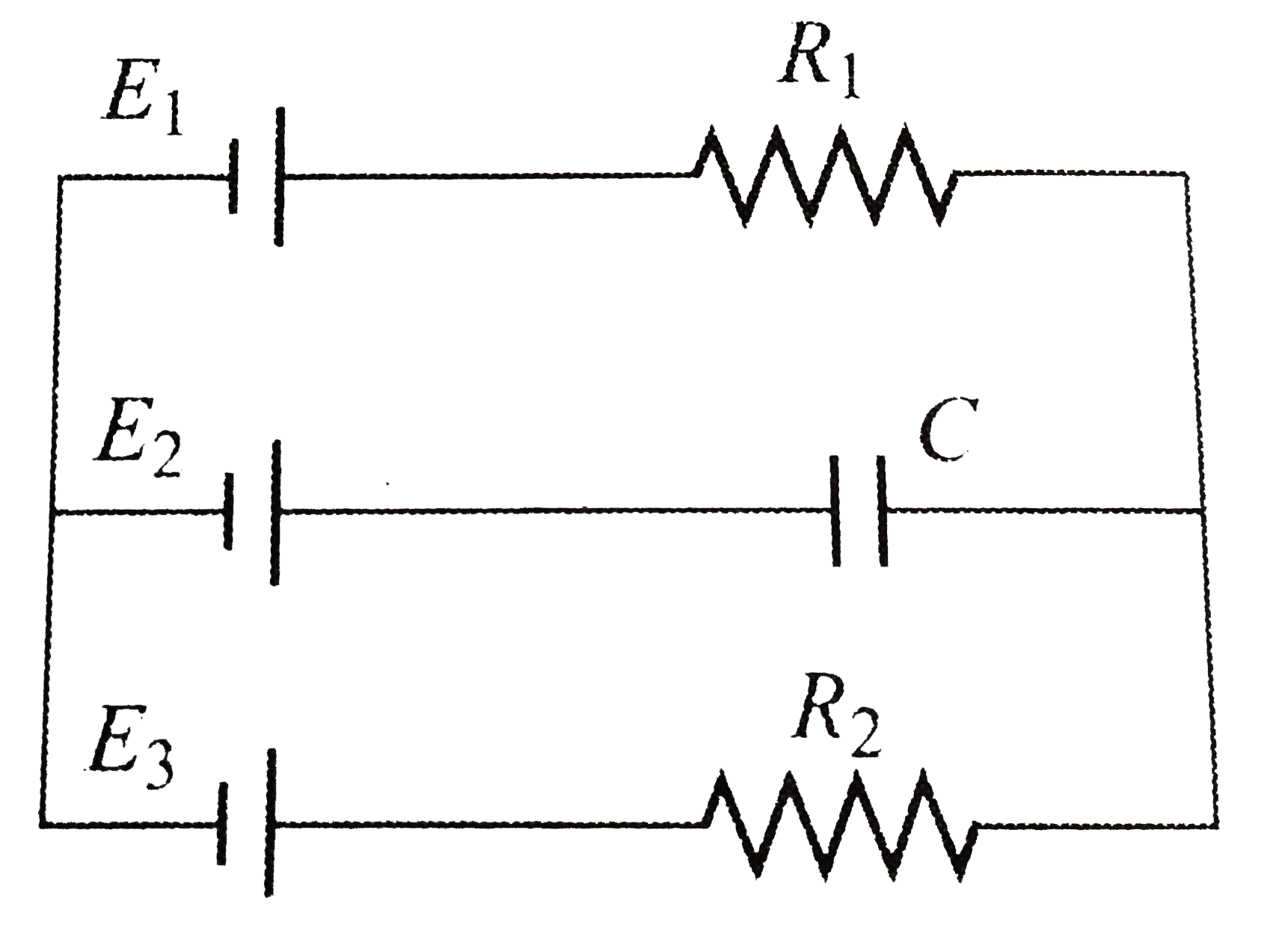
In the circuit shown , the batteries have emf E1=E2=1V,E3=2.5V, and the resistance R1=10Ω,R2=20Ω, Capacitance C=10μF. The charge on the left plate of the charge on the left plate of the capacitor C at steady state is
+2μC
−4μC
−5μC
+12μC
The correct Answer is:C
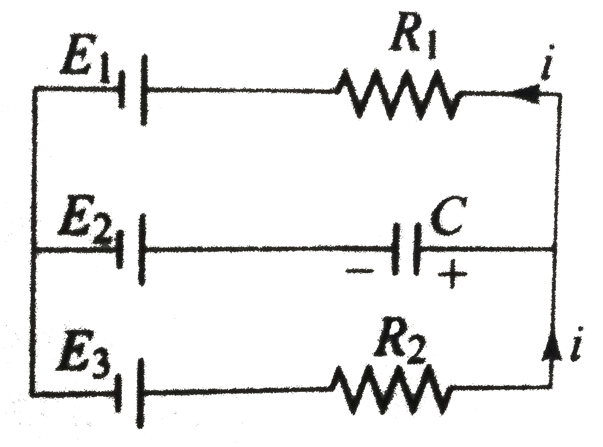
c. i=2.5−130=0.05A
−20i+2.5=Vcapacitor+1
Vcapacitor=0.5V
q(−)=CV=10×0.5=5 .
Similar Questions
In the circuit shown, the batteries have emf E(t)=E2=1 (V),E3=2.5V and the resistance R1=10ohm,R2=20ohmCapacitance C=10μF. The magnitude of charge (in μC ) on the left plate of the capacitor C at steady state is
'(##CEN_KSR_PHY_JEE_CO20_E01_022_Q17##)'
View SolutionFind a potential difference φA−φB between the plates of a capacitor C in the circuit shown in Fig, if the sources have emf'sE1=40V,E2=1.0V and the resistances are equal to R1=10Ω,R2=20Ω, and R3=30Ω. The internal resistances of the sources are negligble.

View Solution
Knowledge Check
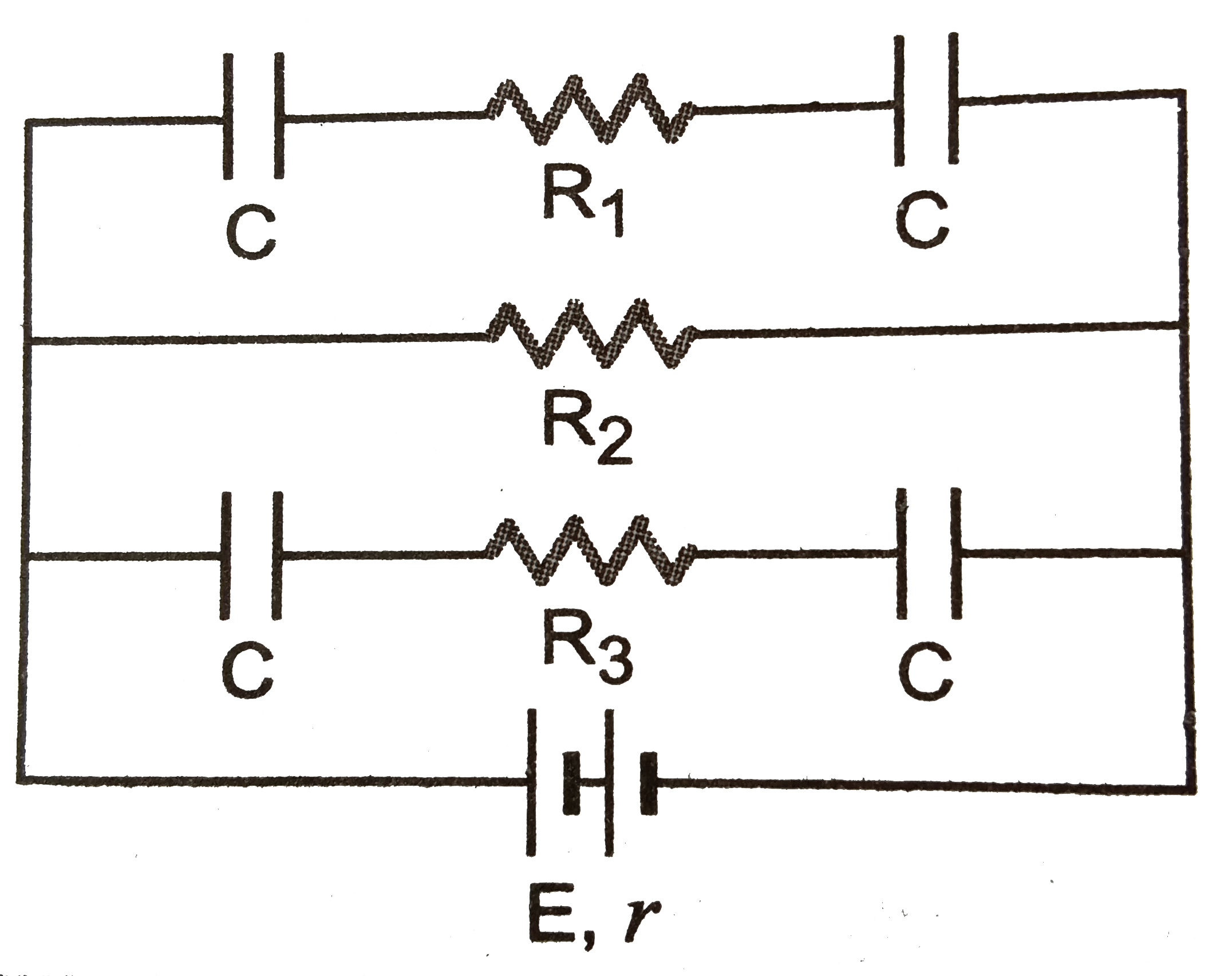
In Fig, E=5 volt , r=1Ω,R2=4Ω,R1=R3=1Ω and C=3μF. Then the numbercal value of the charge on each plate of the capacitor is
 A24μCB12μCC6μCD3μC
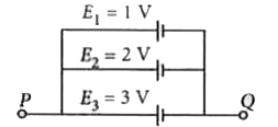
A circuit consists of three batteries of emf E1 = 1 V, E2=2VandE3=3V and internal resistances 1Ω,2Ωand1Ω respectively which are connected in parallel as shown in the figure. The potential difference between points P and Q is
 A1.0VB2.0VC2.2VD3.0V
In the given circuit, R1 = 10Ω R2=6Omega and E = 10V, then correct statement is
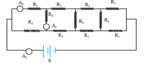 AEffective resistance of the circuit is 10ΩBR Reading of A1 is 1//2 amp.CReading of A2 is 1//2 ampDReading of A3 is 1//8 amp.
In the circuit shown in Fig, the sources have emf'sξ1=1.5V,ξ2=2.0V,ξ3=2.5V , and the resistances are equal to R1=10Ω,R2=20Ω,R3=30Ω. The internal resistances of the sources are negligible. Find : ltbrtgt (a) the current flowing thorugh teh resistance R1 ,
(b) a potential differences φA−φB between the points A and B between the points A and B.

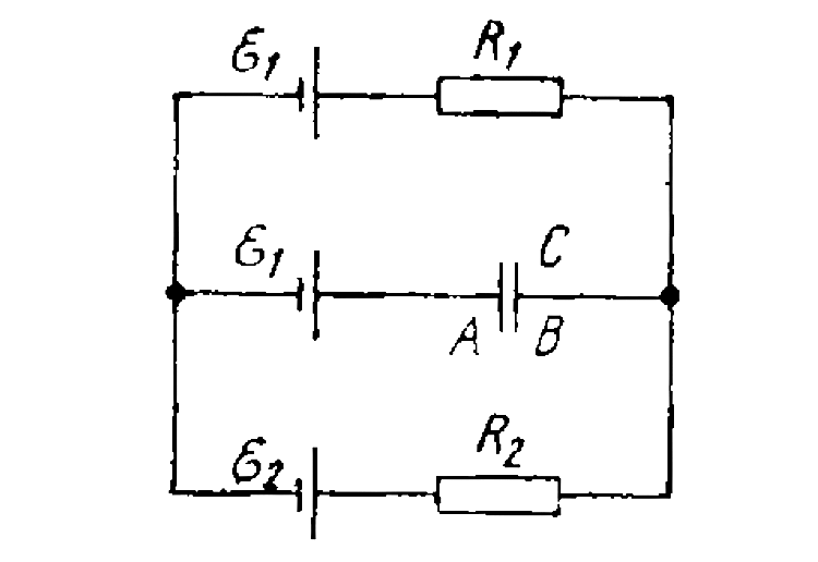
View SolutionIn the circuit shown in Fig the sources have emf'sξ1=1.0V and ξ2=2.5V and teh resistances have the values R1=10Ω and R_(2) = 20 Omega. The internal resistances of the sources are neglibile . Find a potential differences φA−φB between the plates A and B of the capacitance C.
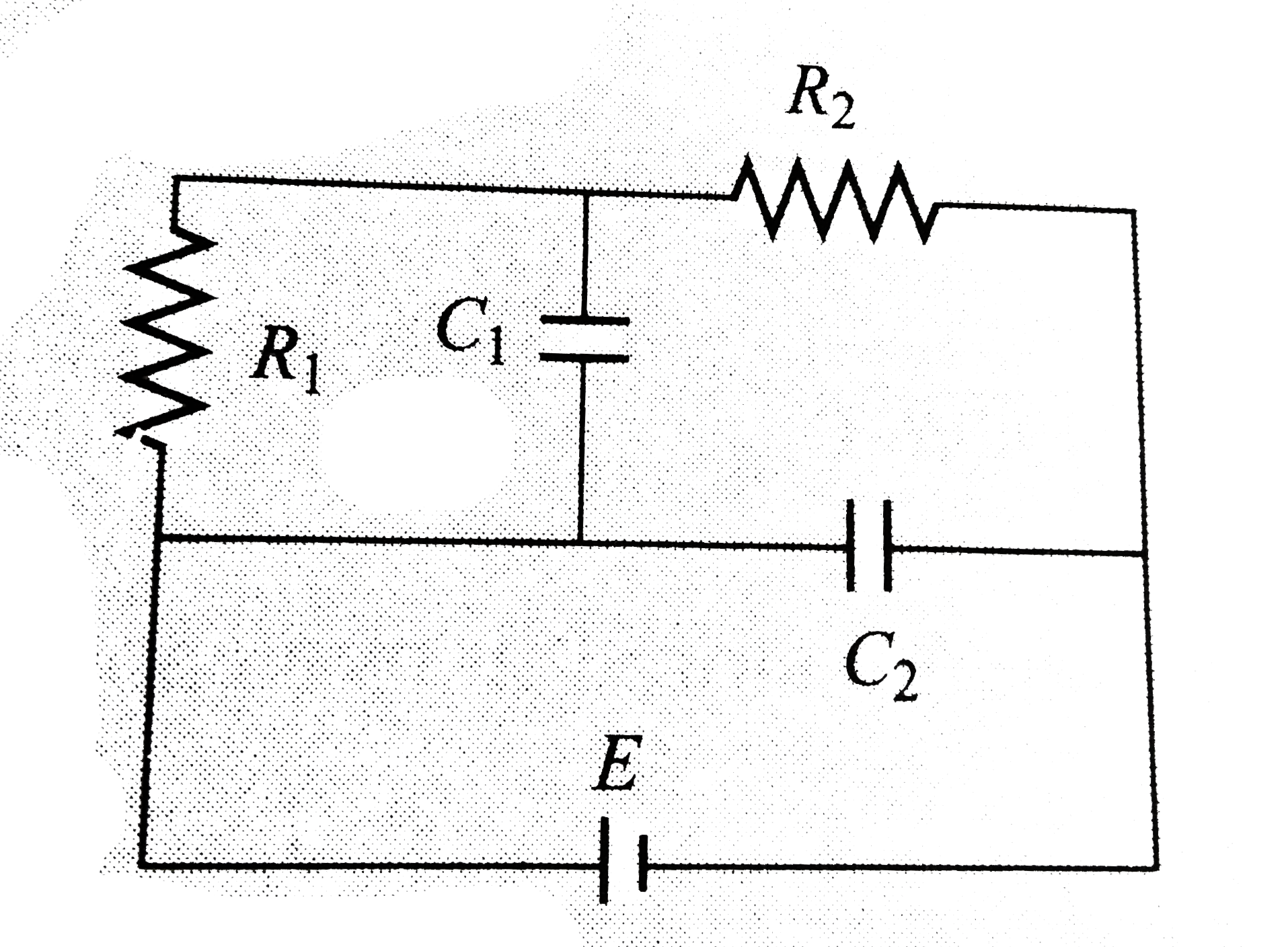
View SolutionIn the circuit shown in fig. R1=10Ω,R2=Ω,C1=1μF,C2=2μF, and E =6V. Calculate the charge on each capactor in the stedy state.
View SolutionIn the figure shown below, the charge on the left plate of the 10μF capacitor is −30μF. The change on the right plate of the 6μF capacitor is:

View SolutionIn the circuit shown in figure, R(1)=1Ω,R2=2Ω,C1=1μF,C2=2μF and E=6V. Calculate charge on each capacitor in steady state
View Solution
