In the circuit shown in fig. R1=10Ω,R2=Ω,C1=1μF,C2=2μF, and E =6V. Calculate the charge on each capactor in the stedy state.
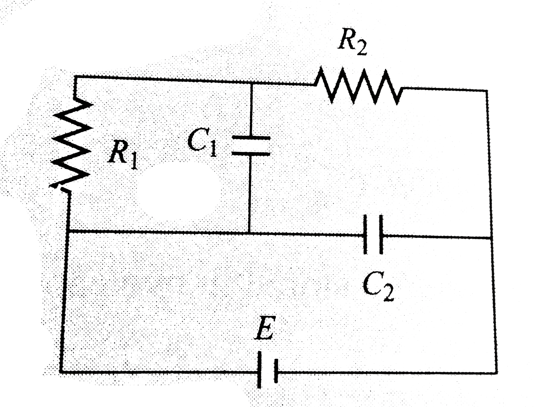
I=ER1+R2=610+20=15A
q1=C1V1=C1IR1=1×15×10=2μC
q2=C2V2=2×6=12μC

Topper's Solved these Questions
- ELECTRIC CURRENT AND CIRCUITBook:CENGAGE PHYSICSChapter:ELECTRIC CURRENT AND CIRCUITExercise:Subjective
Explore 29 Videos
- ELECTRIC CURRENT AND CIRCUITBook:CENGAGE PHYSICSChapter:ELECTRIC CURRENT AND CIRCUITExercise:Single Correct
Explore 72 Videos
- ELECTRIC CURRENT AND CIRCUITBook:CENGAGE PHYSICSChapter:ELECTRIC CURRENT AND CIRCUITExercise:Exercise 5.1
Explore 28 Videos
- ELECTRIC CURRENT & CIRCUITSBook:CENGAGE PHYSICSChapter:ELECTRIC CURRENT & CIRCUITSExercise:Kirchhoff s law and simple circuits
Explore 15 Videos
- ELECTRIC FLUX AND GAUSS LAWBook:CENGAGE PHYSICSChapter:ELECTRIC FLUX AND GAUSS LAWExercise:MCQ s
Explore 38 Videos
Similar Questions
In the circuit shown in figure, R(1)=1Ω,R2=2Ω,C1=1μF,C2=2μF and E=6V. Calculate charge on each capacitor in steady state
View SolutionFind a potentail difference φ1−φ2 between points 1 and 2 of the circuit shown in Fig if R11=10Ω,R2=20Ω,E1=5.0V, and E2=2.0V. The internal resisances of the current sources are negligible.

View Solution
Knowledge Check
In the circuit shown below E1=4.0V,R1=2Ω,E2=6.0V,R2=4Ω and R3=2Ω. The current I1 is
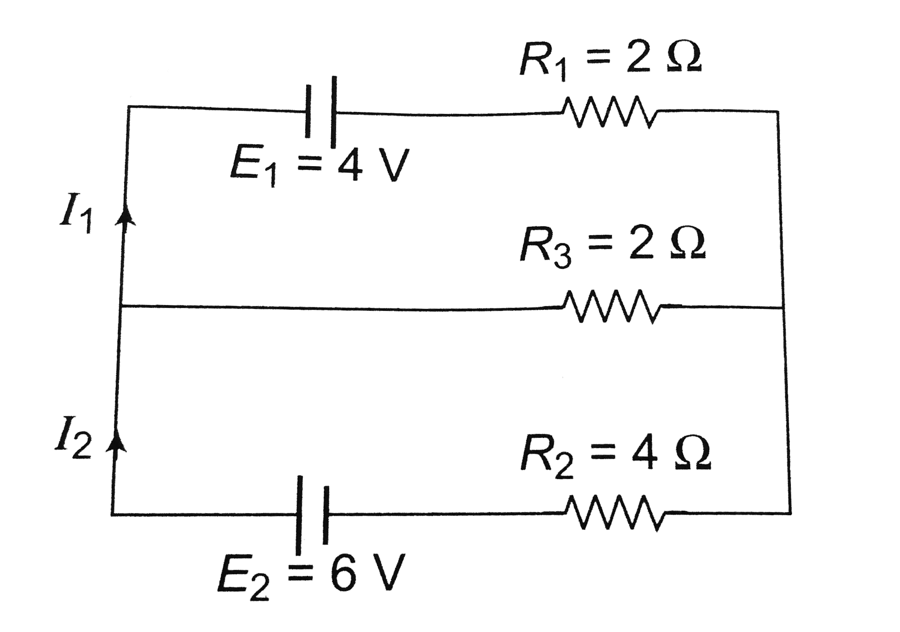 A1.6AB1.8AC1.25AD1.0A
In the circuit shown in figure C1=C2=2μF. Then charge stored in
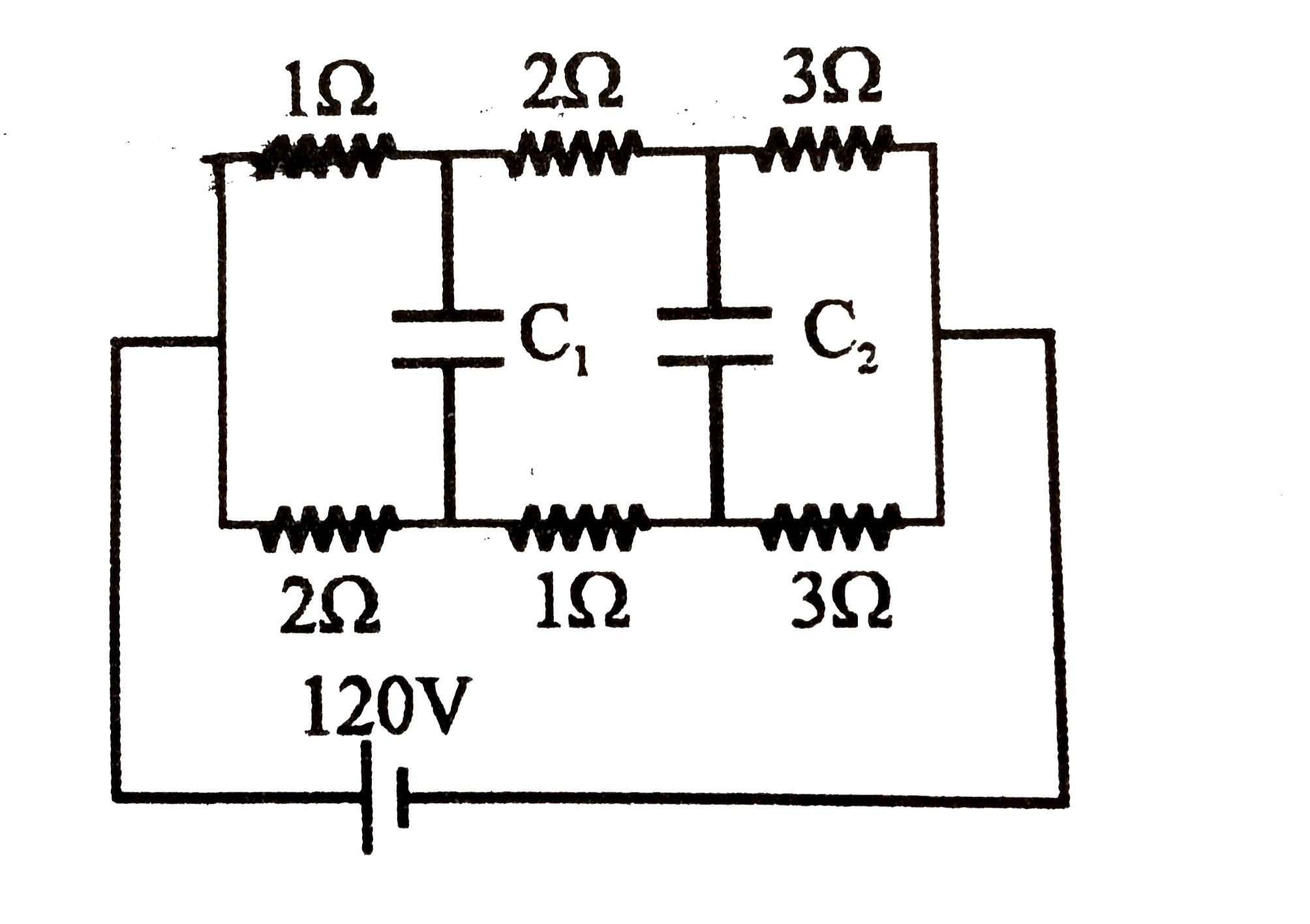 Acapacitor C1 is zeroBcapacitor C2 is zeroCboth capacitor is zeroDcapacitor C1 is 40μC
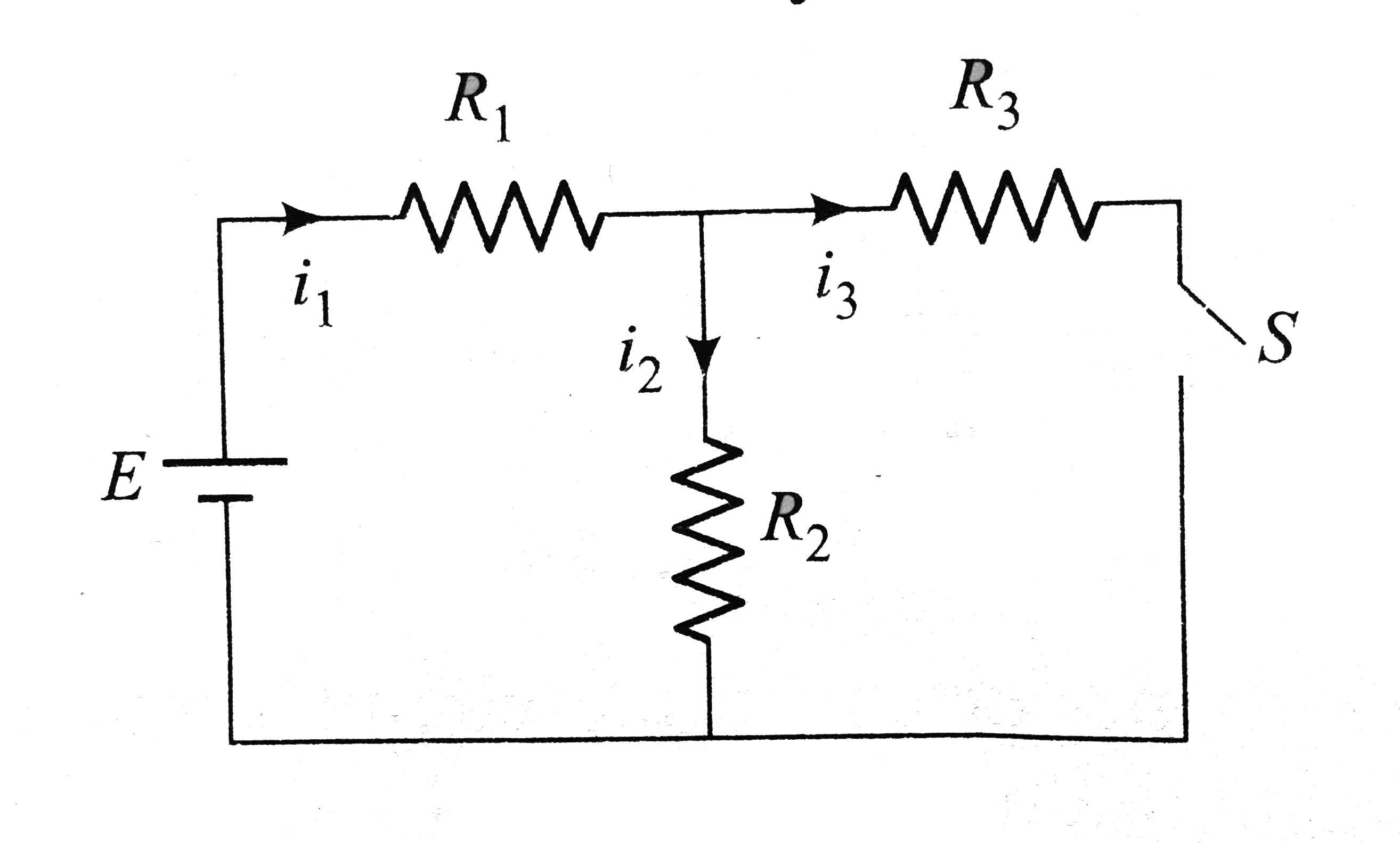
In the circuit shown in adjoining fig E =10V, R1=1ΩR2=2Ω,R3=3ΩandL=2H. Calculate the value of current i1,i2andi3 immidiately after key S is closed :-
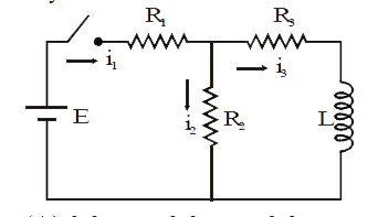 A3.3 amp, 3.3 amp, 3.3 ampB3.3 amp, 3.3 amp, 0 ampC3.3 amp, 0 amp, 0 ampD3.3 amp , 3.3 amp 1.1 amp
In the circuit R1=4Ω,R2=R3=15ΩR4=30ΩandE=10V Calculate the equivalent resistance of the circuit and current in each resistor
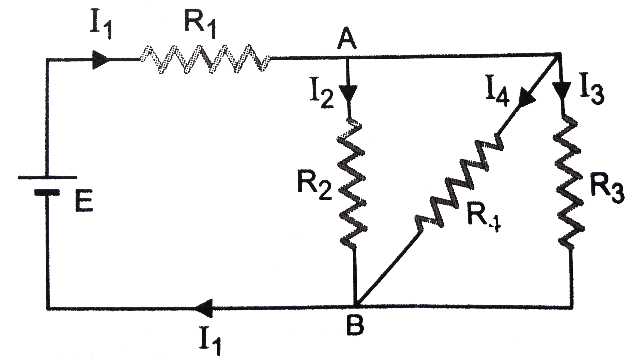
View SolutionIn the circuit shown in Fig. 4.19. R1=100Ω,R2=R3=50Ω,R4=75Ω and E=4.75 V. Work out the equivalent resistance of the circuit and the current in each resistor.
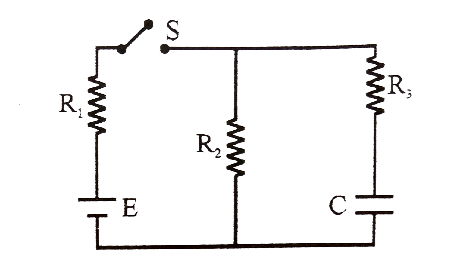
View SolutionIn the circuit shown in figure R1=R1=6R3=300MΩ,C=0.01μF and E−10V. The switch is closed at t=0, find
(a) Charge on capacitor as a function of time
(b) enegry of the capacitor at t=20s
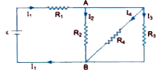
View SolutionIn the circuit shown , R1=4Ω,R2=R3=15Ω,R4=30Ω and ε=10V . Calculate the equivalent resistance of the circuit and the current in each resistor.
View SolutionIn the circuit shows in Fig E=15V, R1=1Ω, R2=1Ω, R3=2Ω, and L=1.5H. The currents flowing through R1,R2,and R3 are i1,i2, and i3, respectively.
After the circuit reaches the steady state,
View Solution

