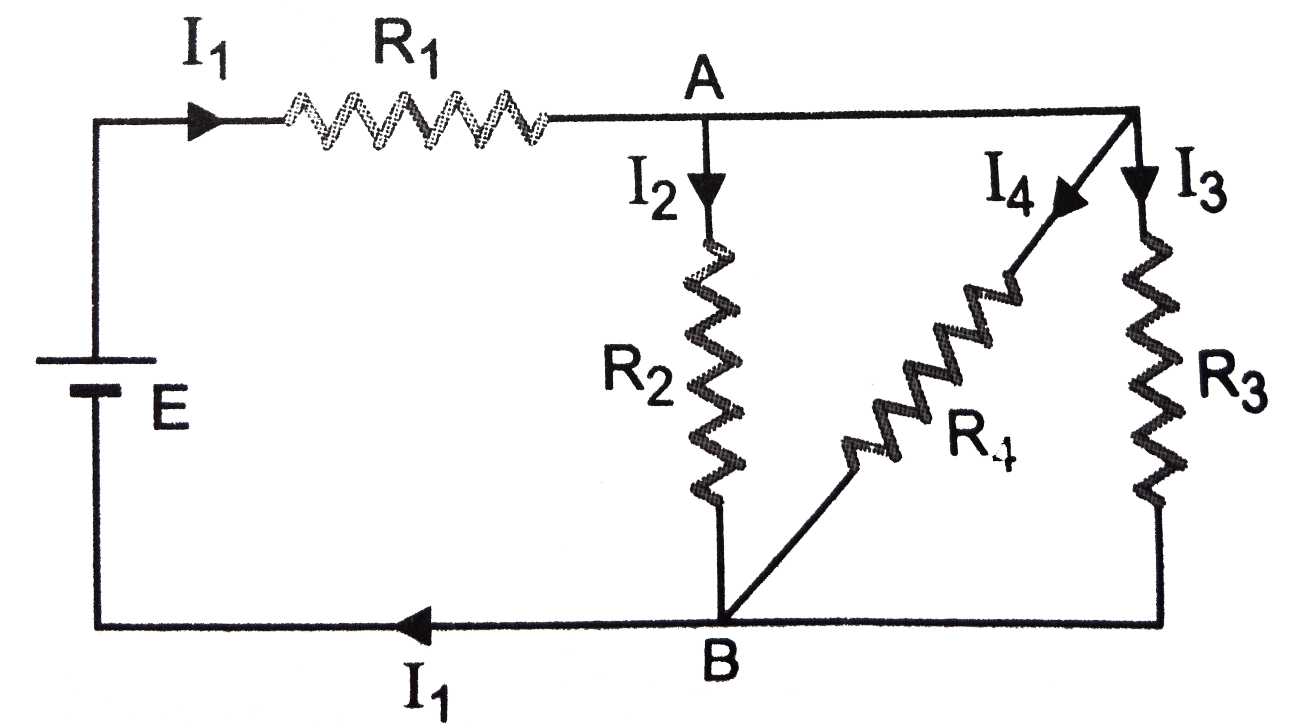
In the circuit Calculate the equivalent resistance of the circuit and current in each resistor
The correct Answer is:(
are in parallel their effective resistance is given by

or
Now equivalent resistance of the circuit is
current
pot diff across
Current through
Current through
Topper's Solved these Questions
- CURRENT ELECTRICITYBook:PRADEEPChapter:CURRENT ELECTRICITYExercise:Jee (main and advance)
Explore 4 Videos
- CURRENT ELECTRICITYBook:PRADEEPChapter:CURRENT ELECTRICITYExercise:Interger Type
Explore 2 Videos
- CURRENT ELECTRICITYBook:PRADEEPChapter:CURRENT ELECTRICITYExercise:Value based
Explore 2 Videos
- COMMUNICATION SYSTEMSBook:PRADEEPChapter:COMMUNICATION SYSTEMSExercise:MODEL TEST PAPER-2
Explore 9 Videos
- DUAL NATURE OF RADIATION AND MATTERBook:PRADEEPChapter:DUAL NATURE OF RADIATION AND MATTERExercise:Exercise
Explore 191 Videos
Similar Questions
In the circuit shown , R1=4Ω,R2=R3=15Ω,R4=30Ω and ε=10V . Calculate the equivalent resistance of the circuit and the current in each resistor.
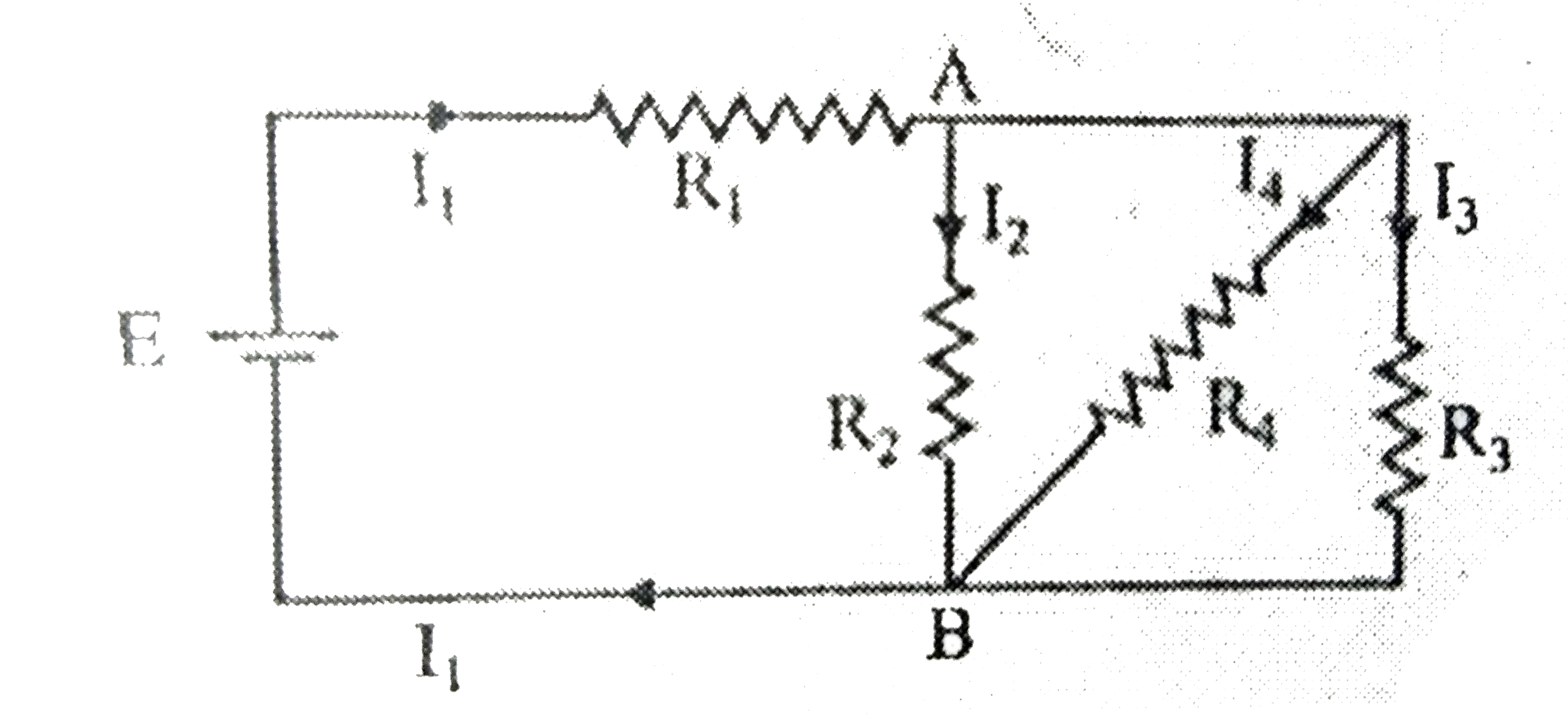
View SolutionIn the circuit shown, R1=4Ω,R2=R3=15Ω,R4=30ΩandE=10V. Caculate the equivalent resistance of te circuit and the current in each resistor.
View Solution
Knowledge Check
In the R1=10Ω,R2=20Ω,R3=40ΩR4=80Ω and VA=5V,VB=10V,Vc=20V,VD=15V The current in the resistance R1 will be
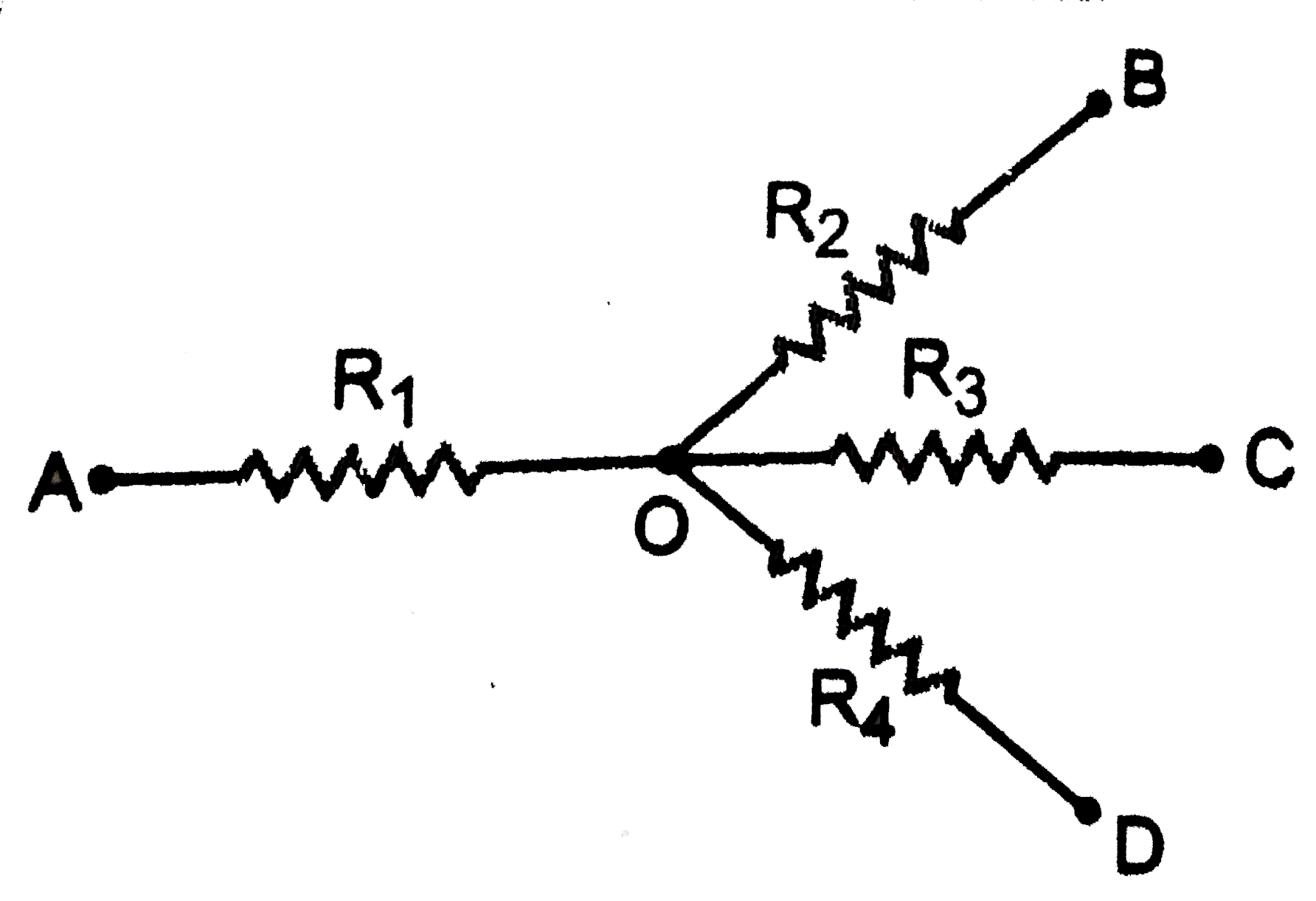 A0.4A toward OB0.4A away from OC0.8A toward OD0.8A toward O
In the given circuit, R1 = 10Ω R2=6Omega and E = 10V, then correct statement is
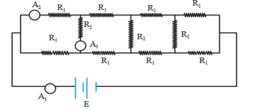 AEffective resistance of the circuit is 10ΩBR Reading of A1 is 1//2 amp.CReading of A2 is 1//2 ampDReading of A3 is 1//8 amp.
In the circuit shown in Fig. 4.19. R1=100Ω,R2=R3=50Ω,R4=75Ω and E=4.75 V. Work out the equivalent resistance of the circuit and the current in each resistor.
View SolutionIn the circuit shown, R1=2Ω,R2=R3=10ΩandE=6V. Work out the equivalent resistance of the circuit and the current in each resistor.
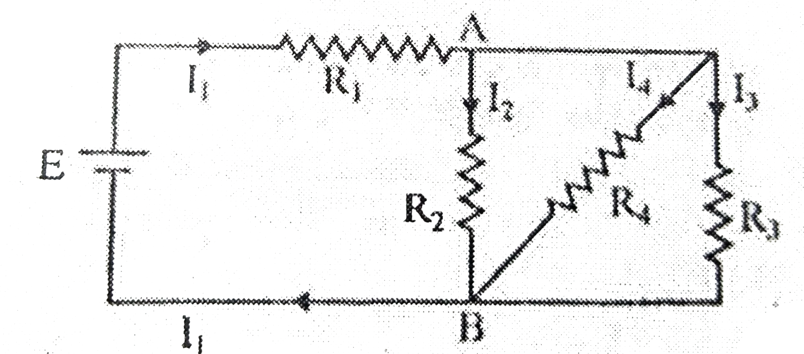
View SolutionIn the circuit given E = 6.0 volt, R1=100Ω,R2=R3=50Ω and R4=75Ω. The equivalent resistance of the circuit, in ohms is
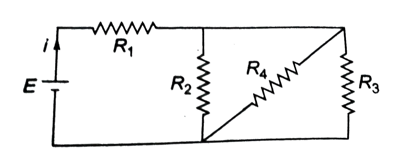
View SolutionIn the circuit shown in fig. R1=10Ω,R2=Ω,C1=1μF,C2=2μF, and E =6V. Calculate the charge on each capactor in the stedy state.
View Solution(a) Resistors given as R1,R2andR3 are connected in series to a battery V. Draw the circuit diagram showing the arrangement. Derive an expression for the equivalent resistance of the combination.
(b) If R1=10Ω,R2=20ΩandR3=30Ω, calculate the effective resistance when they are connected in series to a battery of 6 V. Also find the current flowing in the circuit.
View SolutionFind a potentail difference φ1−φ2 between points 1 and 2 of the circuit shown in Fig if R11=10Ω,R2=20Ω,E1=5.0V, and E2=2.0V. The internal resisances of the current sources are negligible.

View Solution

