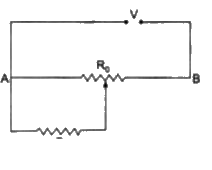
Fig. illustrates a potentiometric circuit by means of which we can very a voltage V applied to a certain device possessing a resistance R. The potentiometer has a length l and a resistance R0 and voltage V0 is applied to its terminals. Find the voltage V fed to the device as a funciton of distanace x. Analyse separately the case R>>R0.

Total resistanace =l−xlR0+R.xR0lR+xR0l
=l−xlR0+xRR0lR+xR0
=R0[1−xl+xRlR+xR0]
Then V=V0xRlR+xR0/(1−xl+xRxR0+lR)=V0Rx/{lR+R0x(1−xl)}
For R>>R0,V=V0xl

Topper's Solved these Questions
- ELECTRODYNAMICSBook:IE IRODOV, LA SENA & SS KROTOVChapter:ELECTRODYNAMICSExercise:Constant Magnetic Fiels - Magnetics
Explore 69 Videos
- ELECTRODYNAMICSBook:IE IRODOV, LA SENA & SS KROTOVChapter:ELECTRODYNAMICSExercise:Electromagnetic Induction
Explore 84 Videos
- ELECTRODYNAMICSBook:IE IRODOV, LA SENA & SS KROTOVChapter:ELECTRODYNAMICSExercise:Electric Capacitance - Energy Of An Electric Field
Explore 46 Videos
- ELECTRICITY AND MAGNETISMBook:IE IRODOV, LA SENA & SS KROTOVChapter:ELECTRICITY AND MAGNETISMExercise:All Questions
Explore 6 Videos
- ELECTROMAGNETISMBook:IE IRODOV, LA SENA & SS KROTOVChapter:ELECTROMAGNETISMExercise:All Questions
Explore 24 Videos
Similar Questions
A potentiometer consisting of a uniform wire of length l and resistance R0 is connected to a steady voltage source of V0 find the voltage V supplied by it to a fixed load R as the funciton of the distance x of sliding contact from the higher potential end Analyse the case when RgtgtR0
View SolutionA resistance of R draw current from a potentiometer. The potentiometer wire, AB, has total resistance of R0. A voltage V is supplied to the potentiometer. Derive an expression for the voltage across R when the sliding contact is in the middle of potentiometer wire.

View Solution
Knowledge Check
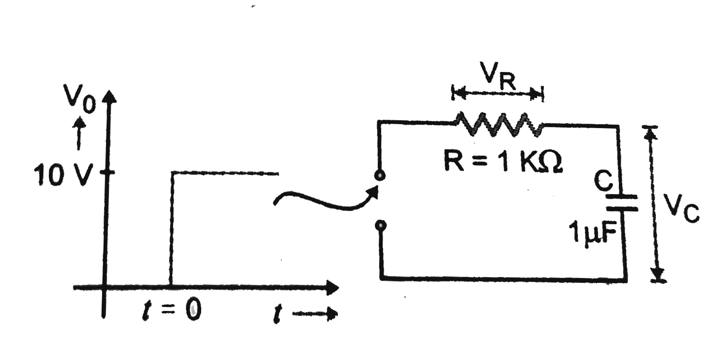
A step voltage V0 is applied to a series combination of R and C as shown Fig. Then
 Aafter sufficienty long time VR=0Bas time passes, VR decreases as (1/t)Cafter 1ms,VC=6.3 volt (approximately)Dinitially, current through R is 10mA.
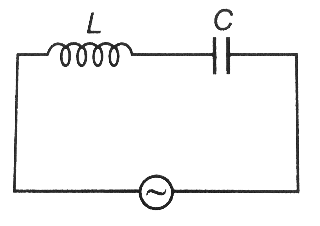
In a series L−C circuit, the applied voltage is V0. if omega is very low, then the voltage drop across the inductor VL and capacitor VC are
 .AVL=V02,VC=V02BVL=0,VC=V0CVL=V0,VC=0DVL=−VC=V02
When a voltage V=V0 cos ωt is applied across a resistor of resistance R, the average power dissipated per cycle in the resistor is given by
AV0√2RBV0√2ωRCV202RDV202ωR
A resistance of RΩ draws current from a potentiometer as shown in Fig. The potentiometer has a total resistance R0Ω. A voltage Vis supplied to the potentiometer. Derive an expression for the voltage across R when the sliding contact is in the middle of the potentiometer.

View SolutionA circuit consisting of a capacitor with capacitance C and a resistance R connected in series was connected at the moment t=0 to a source of ac voltage V=Vmcosωt . Find the current in the circuit as a function of time t.
View SolutionIn a series resonant circuit, the ac voltage across resistance R, inductance L and capacitance C are VR=4V,VL=10V and VC=7V respectively. Find the voltage applied to the circuit.
View SolutionIn a series resonant circuit, the ac voltage across resistance R, inductance L and capacitance C are VR=4V,VL=10V and VC=7V respectively. Find the voltage applied to the circuit.
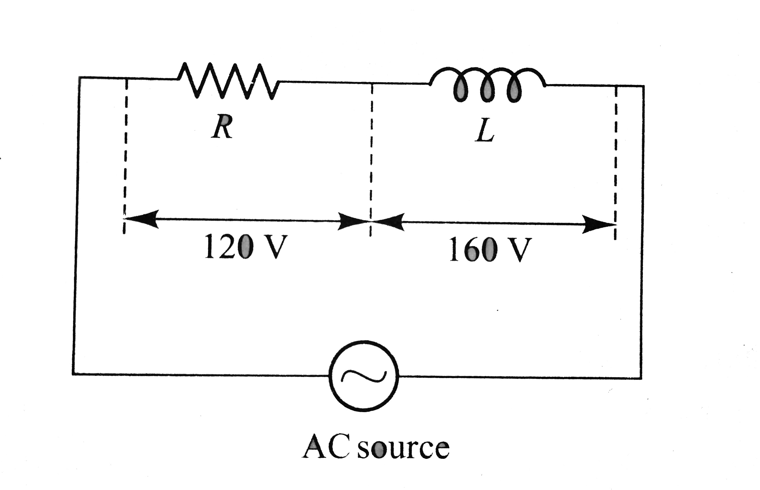
View SolutionThe circuit given in fig. has a resistanceless choke coil L and a resistance R. The voltage across R and L are also given in the figure. The virtual value of the applied voltage is

View Solution

