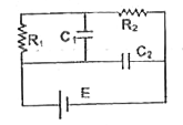
In the circuit in figure emfE1=14V (internal resistance r1=1Ω),R1=6ΩR2=3.5Ω,emfE2=12v (internal resistance r2=0.5Ω),C1=4μF and C2=2μF.

The potential difference across R1 is
2V
12V
14V
26V
The correct Answer is:B
Step by step video, text & image solution for In the circuit in figure emf E_(1) = 14V (internal resistance r_(1) = 1Omega),R_(1) = 6Omega R_(2) = 3.5 Omega, emf E_(2) = 12v (internal resistance r_(2) = 0.5Omega), C_(1) = 4muF and C_(2) = 2muF. The potential difference across R_(1) is by Physics experts to help you in doubts & scoring excellent marks in Class 12 exams.
Updated on:21/07/2023Similar Questions
Knowledge Check
In the circuit in figure emfE1=14V (internal resistance r1=1Ω),R1=6ΩR2=3.5Ω,emfE2=12v (internal resistance r2=0.5Ω),C1=4μF and C2=2μF.
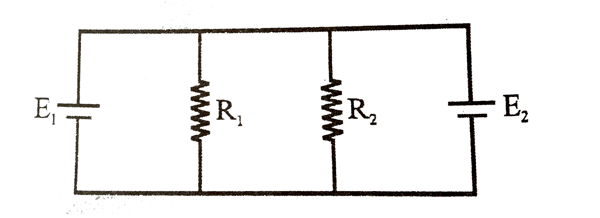
The potential difference across R2 isA10.5VB12.5VC15.0VD26VIn the circuit in figure emfE1=14V (internal resistance r1=1Ω),R1=6ΩR2=3.5Ω,emfE2=12v (internal resistance r2=0.5Ω),C1=4μF and C2=2μF.

The charge on capacitor C2 isA20μCB30μCC40μCD60μCIn the circuit in figure emfE1=14V (internal resistance r1=1Ω),R1=6ΩR2=3.5Ω,emfE2=12v (internal resistance r2=0.5Ω),C1=4μF and C2=2μF.

The potential difference across R1 isA2μFB2/3μFC3μFD4/3μF
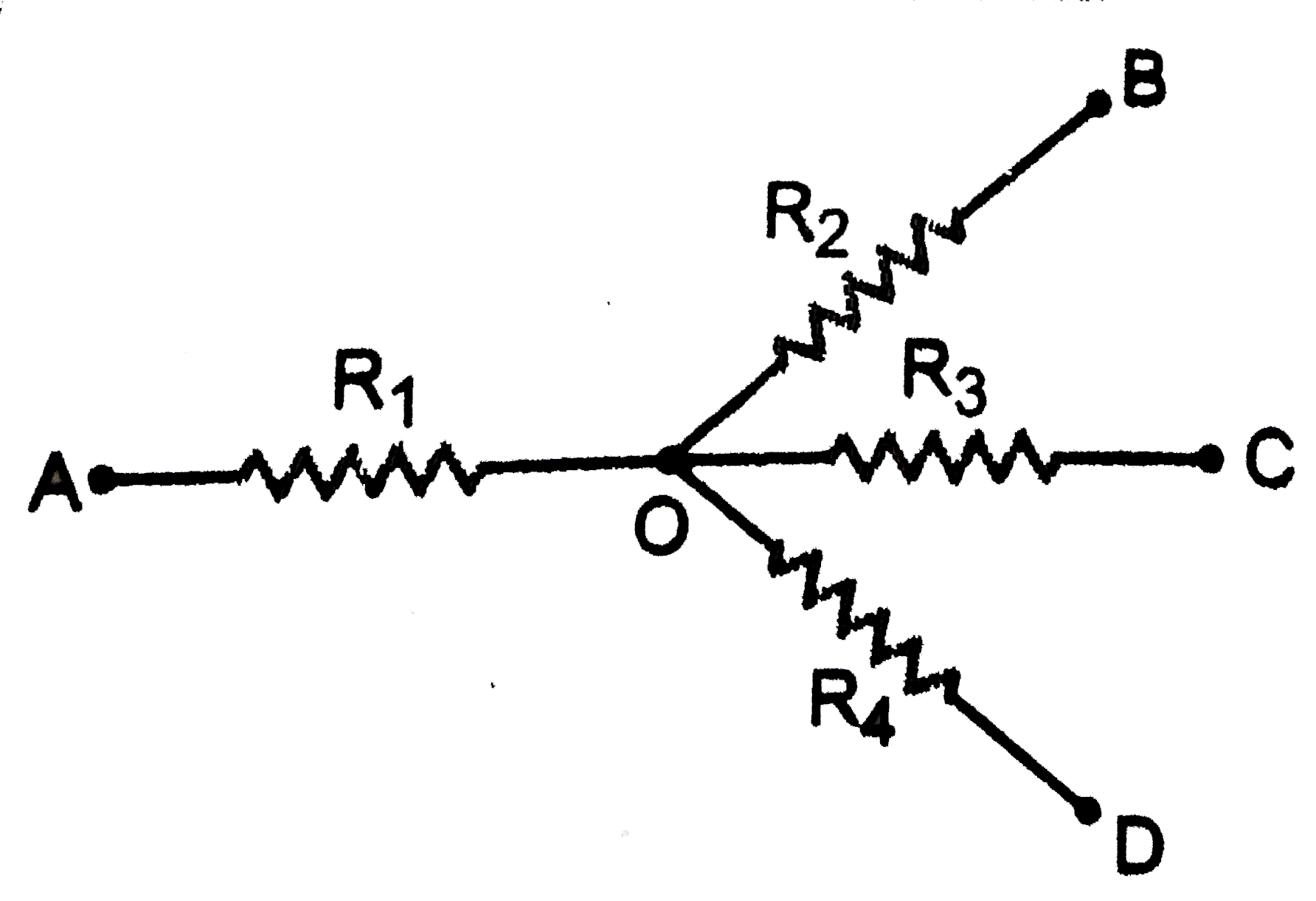
In the R1=10Ω,R2=20Ω,R3=40ΩR4=80Ω and VA=5V,VB=10V,Vc=20V,VD=15V The current in the resistance R1 will be
View SolutionIn the given circuit, R1 = 10Ω R2=6Omega and E = 10V, then correct statement is
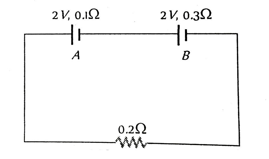
View SolutionThe internal resistances of two cells shown are 0.1Ω and 0.3Ω. If R=0.2Ω, its potential difference across the cell
View SolutionA cell E1 of emf 6V and internal resistance 2Ω is connected with another cell E2 of emf 4V and internal resistance 8Ω (as shown in the figure). The potential difference across points X and Y is :

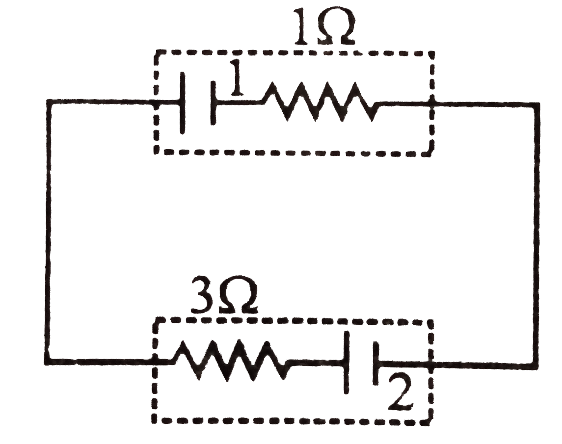
View SolutionIn the figure shown, battery 1 has emf=6V and internal resistance =1Ω. Battery 2 has emf=2V and internal resistance =3Ω. The wires have negligible resistance. What is the potential difference across the teminals of battery 2?
View Solution


