In a series LR circuit, the voltage drop across inductor is 8 volt and across resistor is 6 volt. Then voltage applied and power factor of circuit respectively are:
14V,0.8
10V,0.8
10 V,0.6
14 V,0.6
To solve the problem, we need to find the applied voltage and the power factor of a series LR circuit where the voltage drop across the inductor (V_L) is 8 volts and the voltage drop across the resistor (V_R) is 6 volts.
1. Identify the given values:
- Voltage drop across the inductor, VL=8V
- Voltage drop across the resistor, VR=6V
2. Calculate the applied voltage (V):
In a series LR circuit, the total voltage (V) is given by the vector sum of the voltage drops across the inductor and the resistor:
V=√V2L+V2R
Substituting the given values:
V=√(8V)2+(6V)2
V=√64+36
V=√100
V=10V
3. Calculate the power factor (cos φ):
The power factor (cos φ) in a series LR circuit is given by the ratio of the voltage across the resistor to the total voltage:
Power Factor=cosϕ=VRV
Substituting the known values:
cosϕ=6V10V=0.6
Final Answers:
- The applied voltage is 10V.
- The power factor is 0.6.
- Voltage drop across the inductor, VL=8V
- Voltage drop across the resistor, VR=6V
In a series LR circuit, the total voltage (V) is given by the vector sum of the voltage drops across the inductor and the resistor:
V=√V2L+V2R
Substituting the given values:
V=√(8V)2+(6V)2
V=√64+36
V=√100
V=10V
The power factor (cos φ) in a series LR circuit is given by the ratio of the voltage across the resistor to the total voltage:
Power Factor=cosϕ=VRV
Substituting the known values:
cosϕ=6V10V=0.6
- The applied voltage is 10V.
- The power factor is 0.6.
Topper's Solved these Questions
Similar Questions
In series LCR circuit voltage drop across resistance is 8V, across inductor is 6V and across capacitor is 12V. Then
View SolutionIn series L−C−R circuit, voltge drop across resistance is 8V, across inductor is 6V and across capacitor is 12V. Then,
View SolutionIn series LCR circuit, the phase difference between voltage across L and voltage across C is
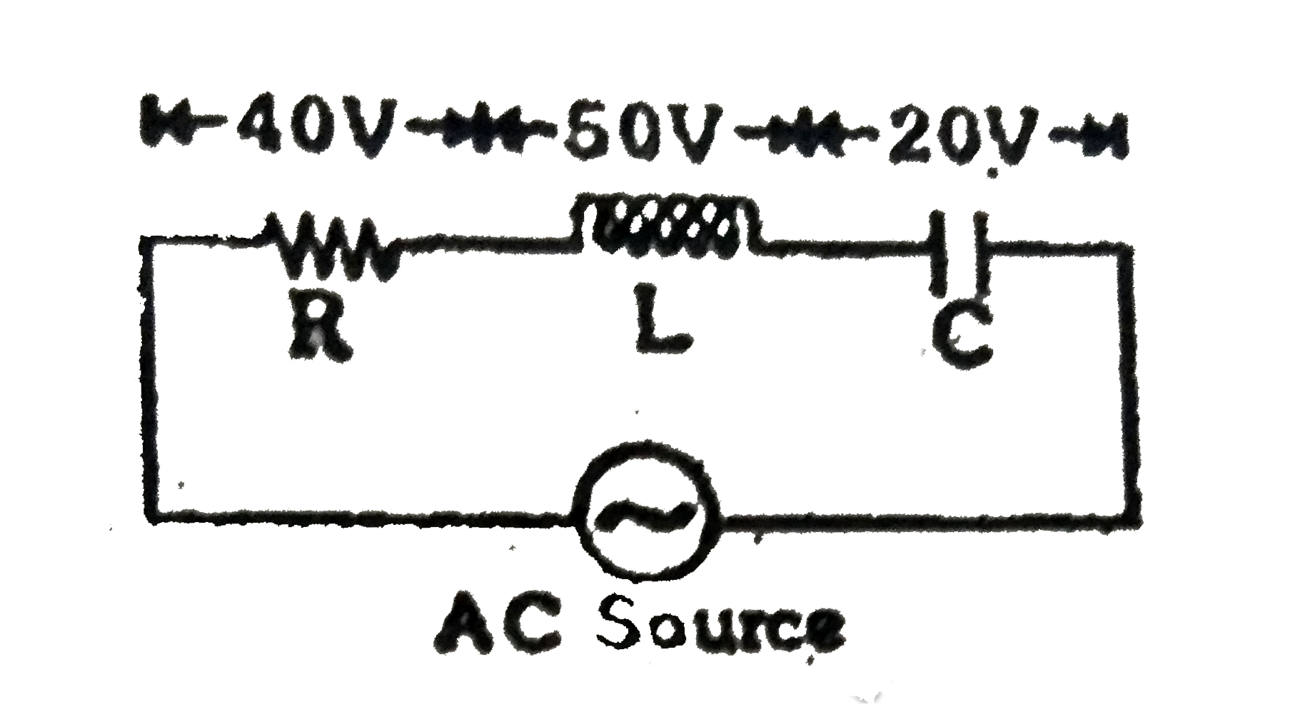
View SolutionIn series LCR circuit, the voltages across R, L and C are shown in the figure. The voltage of applied source

View SolutionIn LCR series circuit source voltage is 120 volt and voltage in inductor 50 volt and resistance is 40 volt then determine voltage in capacitor.
View SolutionIn a series LCR circuit, voltage drop axross L can be more than applied voltage (True/false).
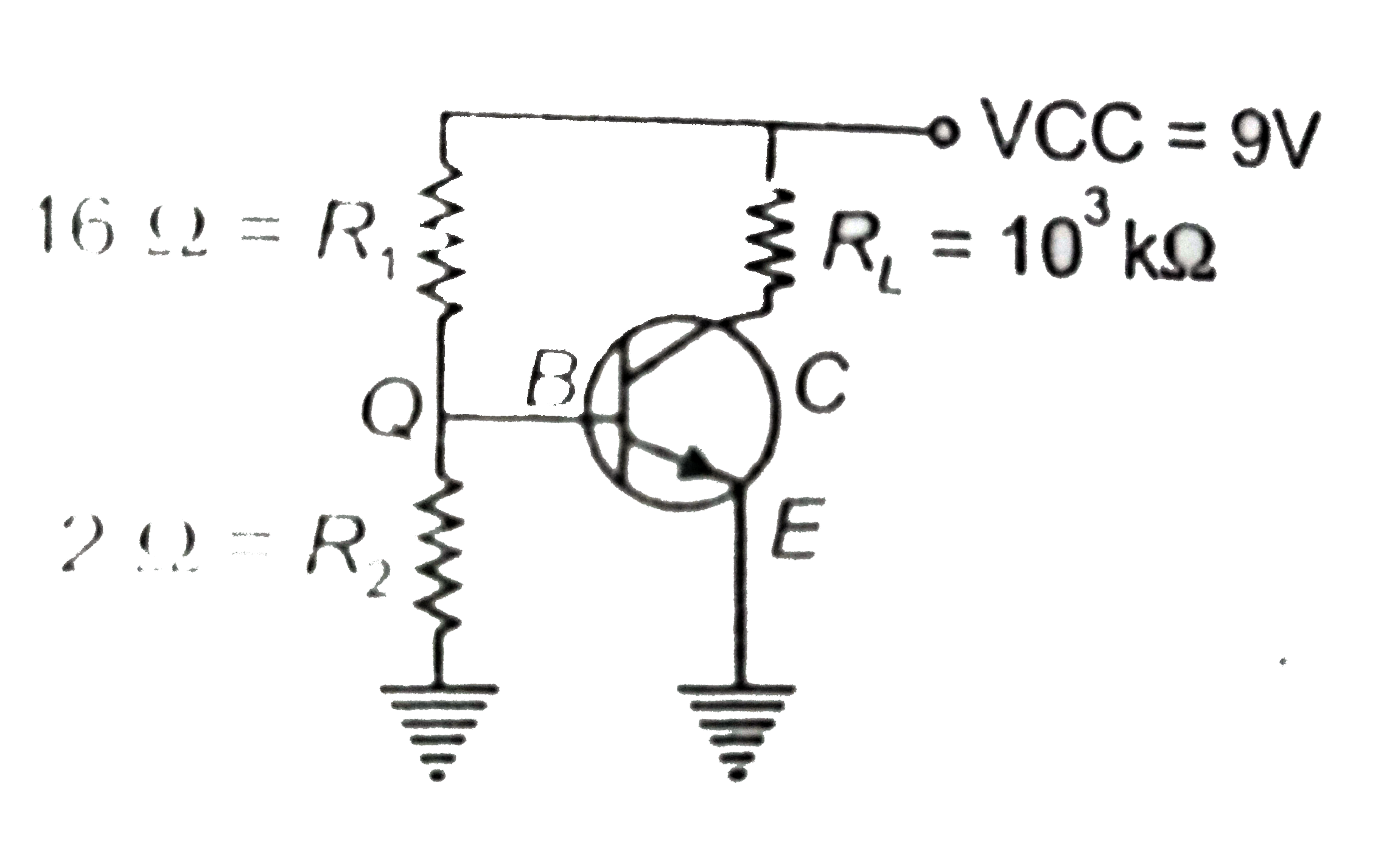
View SolutionIn the given circuit , the voltage across the base emitter junction is

View SolutionWhat is the value of power factor for series LR circuit ?
View SolutionIn a series LCR circuit, the voltages across an inductor, a capacitor and a resistor are 30 V, 30 V, 60 V respectively. What is the phase difference between the applied voltage and the current in the circuit ?
View SolutionIn a series LCR circuit, the voltages across an inductor, a capacitor and a resistor are 30 V, 30 V, 60 V respectively. What is the phase difference between the applied voltage and the current in the circuit ?
View Solution

