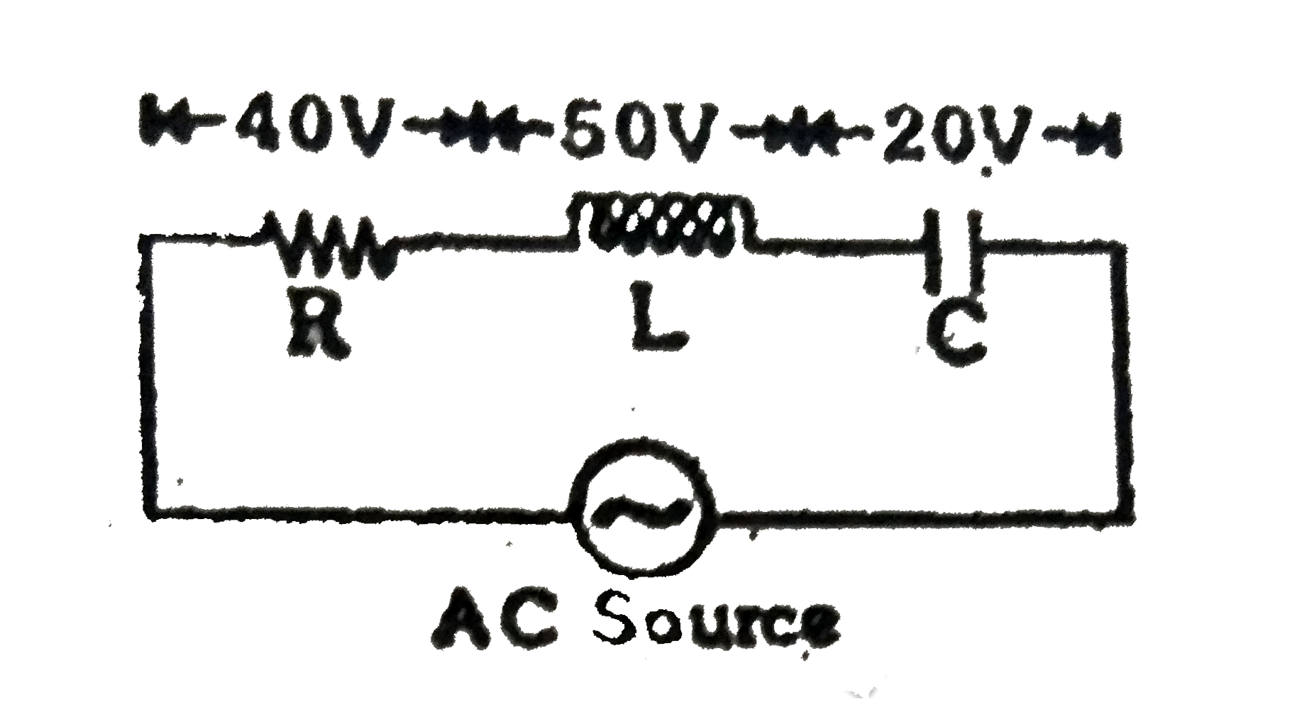
In a series LCR circuit, voltage drop axross L can be more than applied voltage (True/false).
To determine whether the statement "In a series LCR circuit, the voltage drop across L can be more than the applied voltage" is true or false, we can analyze the circuit step by step.
1. Understanding the Circuit:
- In a series LCR circuit, we have an inductor (L), a capacitor (C), and a resistor (R) connected in series to an AC voltage source. The total voltage applied across the circuit is denoted as V.
2. Voltage Drops in the Circuit:
- The voltage drop across the inductor is given by VL=I⋅XL, where I is the current through the circuit and XL is the inductive reactance.
- The inductive reactance XL is given by XL=ωL, where ω is the angular frequency of the AC source.
3. Current in the Circuit:
- The current I in the circuit can be expressed in terms of the total voltage V and the impedance Z of the circuit:
I=VZ
- The impedance Z is calculated as:
Z=√R2+(XL−XC)2
- Here, XC is the capacitive reactance given by XC=1ωC.
4. Calculating Voltage Drop Across Inductor:
- The peak voltage drop across the inductor can be expressed as:
VL=I⋅XL=VZ⋅XL
5. Condition for VL to Exceed V:
- For the voltage drop across the inductor VL to be greater than the applied voltage V, the following condition must hold:
VZ⋅XL>V
- Simplifying this gives:
XL>Z
6. Conclusion:
- If the inductive reactance XL is greater than the impedance Z, then the voltage drop across the inductor can indeed exceed the applied voltage. This situation can occur in certain conditions, such as when the circuit is highly inductive.
Therefore, the statement "In a series LCR circuit, the voltage drop across L can be more than the applied voltage" is True.
- In a series LCR circuit, we have an inductor (L), a capacitor (C), and a resistor (R) connected in series to an AC voltage source. The total voltage applied across the circuit is denoted as V.
- The voltage drop across the inductor is given by VL=I⋅XL, where I is the current through the circuit and XL is the inductive reactance.
- The inductive reactance XL is given by XL=ωL, where ω is the angular frequency of the AC source.
- The current I in the circuit can be expressed in terms of the total voltage V and the impedance Z of the circuit:
I=VZ
- The impedance Z is calculated as:
Z=√R2+(XL−XC)2
- Here, XC is the capacitive reactance given by XC=1ωC.
- The peak voltage drop across the inductor can be expressed as:
VL=I⋅XL=VZ⋅XL
- For the voltage drop across the inductor VL to be greater than the applied voltage V, the following condition must hold:
VZ⋅XL>V
- Simplifying this gives:
XL>Z
- If the inductive reactance XL is greater than the impedance Z, then the voltage drop across the inductor can indeed exceed the applied voltage. This situation can occur in certain conditions, such as when the circuit is highly inductive.
Topper's Solved these Questions
- ALTERNATING CURRENTBOOK - CENGAGE PHYSICS ENGLISHCHAPTER - ALTERNATING CURRENTEXERCISE - Exercises Subjective
15 Videos
- ALTERNATING CURRENTBOOK - CENGAGE PHYSICS ENGLISHCHAPTER - ALTERNATING CURRENTEXERCISE - Exercises Single Correct
63 Videos
- ALTERNATING CURRENTBOOK - CENGAGE PHYSICS ENGLISHCHAPTER - ALTERNATING CURRENTEXERCISE - Solved Examples
6 Videos
- ATOMIC PHYSICSBOOK - CENGAGE PHYSICS ENGLISHCHAPTER - ATOMIC PHYSICSEXERCISE - ddp.4.3
15 Videos
Similar Questions
Knowledge Check
In series LCR circuit, the phase angle between supply voltage and current is
Atanϕ=XL−XCRBtanϕ=RXL−XCCtanϕ=RXL+XCDtanϕ=XL+XCRIn a series LCR circuit, the voltage across the resistance, capacitance and inductance is 10 V each. If the capacitance is short circuited, the voltage across the inductance will be
A10VB10√2VC10√2VD20V
In series LCR AC circuit, the voltage of the source at any instant is equal to
View SolutionIn a series LCR circuit, the voltages across an inductor, a capacitor and a resistor are 30 V, 30 V, 60 V respectively. What is the phase difference between the applied voltage and the current in the circuit ?
View SolutionIn a series LCR circuit, the voltages across an inductor, a capacitor and a resistor are 30 V, 30 V, 60 V respectively. What is the phase difference between the applied voltage and the current in the circuit ?
View SolutionAssertion: In series, L-C-R voltage across capacitor is always less than the applied voltage.
Reason: In series L-C-R circuit, V=√(V2R+(V2L−V2C))
View SolutionIn a series LCR circuit the rms voltage across the inductance , capacitance and resistance are respectively 4 V, 8 V and 5 V . The RMS voltage of the AC source in the circuit is
View SolutionIn a series L−C−R circuit, currenrt in the circuit is 11A when the applied voltage is 220V. voltage across the caspcitor is 200V. If the value of resistor is 20Ω, then the voltage across the unknown inductor is
View Solution

