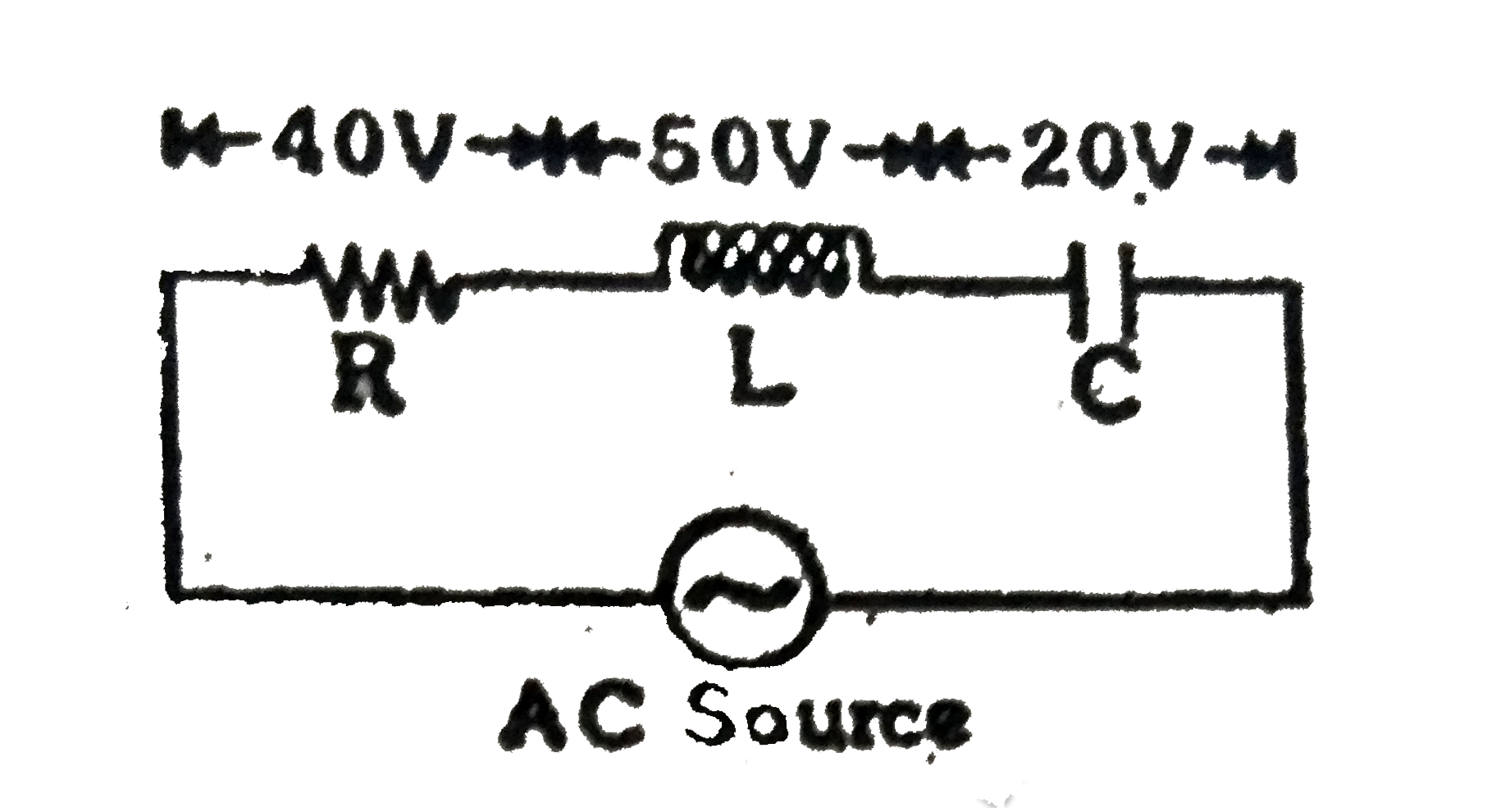
Assertion: In series, L-C-R voltage across capacitor is always less than the applied voltage.
Reason: In series L-C-R circuit, V=√(V2R+(V2L−V2C))
If both Assertion and Reason are true and Reason is the correct explanation of Assertion.
If both Assertion and Reason are true but Reason is not the correct explanation of Assertion.
If Assertion is true but Reason is false.
If Assertion is false but Reason is true.
The correct Answer is:D
To solve the problem, we need to analyze the assertion and reason provided in the question regarding a series L-C-R circuit.
Step 1: Understand the Assertion
The assertion states that "In series, L-C-R voltage across the capacitor is always less than the applied voltage." We need to determine if this statement is true or false.
Step 2: Analyze the Reason
The reason provided is that "In series L-C-R circuit, V = sqrt((V_R^2 + (V_L^2 - V_C^2)))". This equation relates the total voltage (V) in the circuit to the voltages across the resistor (V_R), inductor (V_L), and capacitor (V_C).
Step 3: Apply the Voltage Relationship
In a series L-C-R circuit, the total voltage (V) is given by:
V2=V2R+(VL−VC)2
This implies that:
V=√V2R+(VL−VC)2
Step 4: Analyze the Capacitor Voltage
From the equation, we can see that the voltage across the capacitor (V_C) is influenced by the voltages across the inductor (V_L) and the resistor (V_R). The relationship shows that V_C can vary depending on the values of V_L and V_R.
Step 5: Determine the Validity of the Assertion
The assertion claims that V_C is always less than V. However, since V_C can be calculated as:
VC=VL−√V2−V2R
it is possible for V_C to be greater than V if V_L is sufficiently large compared to V_R. Therefore, the assertion is not universally true.
Conclusion
- Assertion: False (V_C can be greater than V)
- Reason: True (The equation accurately describes the relationship in the circuit)
Final Answer
The assertion is false, and the reason is true.
---
The assertion states that "In series, L-C-R voltage across the capacitor is always less than the applied voltage." We need to determine if this statement is true or false.
The reason provided is that "In series L-C-R circuit, V = sqrt((V_R^2 + (V_L^2 - V_C^2)))". This equation relates the total voltage (V) in the circuit to the voltages across the resistor (V_R), inductor (V_L), and capacitor (V_C).
In a series L-C-R circuit, the total voltage (V) is given by:
V2=V2R+(VL−VC)2
V=√V2R+(VL−VC)2
From the equation, we can see that the voltage across the capacitor (V_C) is influenced by the voltages across the inductor (V_L) and the resistor (V_R). The relationship shows that V_C can vary depending on the values of V_L and V_R.
The assertion claims that V_C is always less than V. However, since V_C can be calculated as:
VC=VL−√V2−V2R
it is possible for V_C to be greater than V if V_L is sufficiently large compared to V_R. Therefore, the assertion is not universally true.
- Assertion: False (V_C can be greater than V)
- Reason: True (The equation accurately describes the relationship in the circuit)
The assertion is false, and the reason is true.
Similar Questions
In L−C−R series circuit
View SolutionIn L−C−R series AC circuit,
View SolutionIn an L-C-R series, AC circuit at resonance
View SolutionIn series LCR circuit, the voltages across R, L and C are shown in the figure. The voltage of applied source

View SolutionAssertion: In an AC circuit, potential difference across the capacitor may be greater than the applied voltage.
Reason : VC=IXC, wheereas V=IZ and XC can be greater than Z also.
View SolutionA series L-C-R circuit is operated at resonance . Then
View SolutionIn series L−C−R circuit, voltge drop across resistance is 8V, across inductor is 6V and across capacitor is 12V. Then,
View SolutionIn a series LCR, AC circuit, if VL=800, VC=1600V and applied voltage is 1000V, then power factor is
View SolutionIn series LCR circuit, the phase difference between voltage across L and voltage across C is
View SolutionIn series LCR circuit voltage drop across resistance is 8V, across inductor is 6V and across capacitor is 12V. Then
View Solution