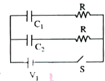
In the circuit shown in figure C1=2C2. Capacitance C1 is charged to a potential of V. The current in the circuit just after the switch S is closed is

0
2V/R
∞
V/2R
The correct Answer is:D
Here, I1=VRe−t/RC,I2=VRe−t/2RC
∴I1I2=e−t/RC+t/2RC=e−t/2RC=1et/2RC
From this expression, it is clear that when t increases, ratio
decrease.
Topper's Solved these Questions
- ELECTRIC CURRENT AND CIRCUITBOOK - CENGAGE PHYSICS ENGLISHCHAPTER - ELECTRIC CURRENT AND CIRCUITEXERCISE - Multiple Correct
16 Videos
- ELECTRIC CURRENT AND CIRCUITBOOK - CENGAGE PHYSICS ENGLISHCHAPTER - ELECTRIC CURRENT AND CIRCUITEXERCISE - Comprehension
35 Videos
- ELECTRIC CURRENT AND CIRCUITBOOK - CENGAGE PHYSICS ENGLISHCHAPTER - ELECTRIC CURRENT AND CIRCUITEXERCISE - Subjective
29 Videos
- ELECTRIC CURRENT & CIRCUITSBOOK - CENGAGE PHYSICS ENGLISHCHAPTER - ELECTRIC CURRENT & CIRCUITSEXERCISE - Kirchhoff s law and simple circuits
15 Videos
- ELECTRIC FLUX AND GAUSS LAWBOOK - CENGAGE PHYSICS ENGLISHCHAPTER - ELECTRIC FLUX AND GAUSS LAWEXERCISE - MCQ s
38 Videos
Similar Questions
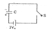
n the circuit shown in the figure, the capacitor C is charged to a potential Vo The heat generated and charge flow, in the circuit to when the switch S is closed, is
View SolutionIn which of the following circuits is the current maximum just after the switch S is closed?

View SolutionThe circuit consists of two resistors (of resistance R1=20Ω and R2=10Ω), a capacitor (of capacitance C=10μF) and two ideal cells. In the circuit shown the capacitor is in steady state and the switch S is open
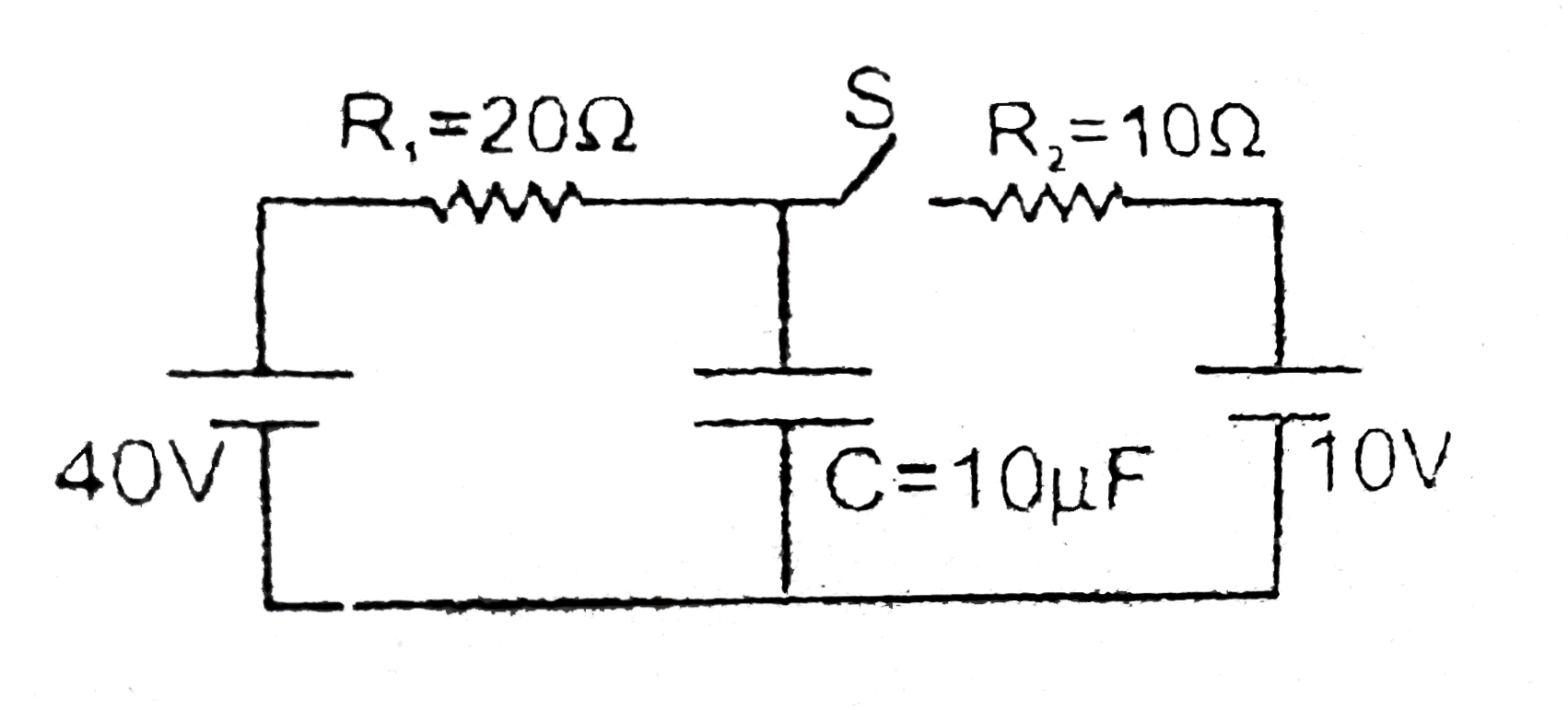
The current through the resistor R2 just after the switch S is closed is :
View SolutionIn the following circuit the value of current i through the battery just after switch S is closed is
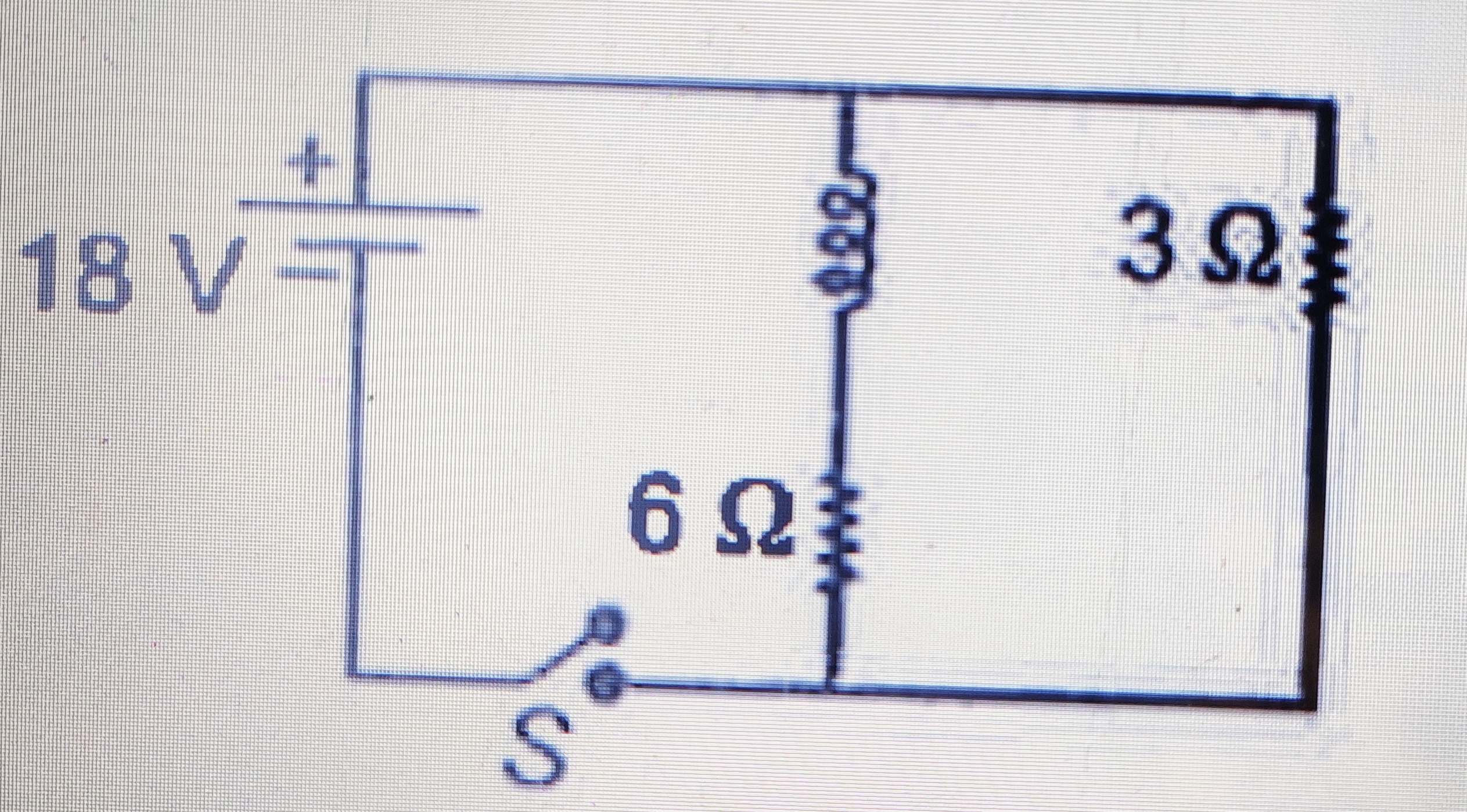
View SolutionIn the circuit diagram the current through the battery immediately after the switch S is closed is
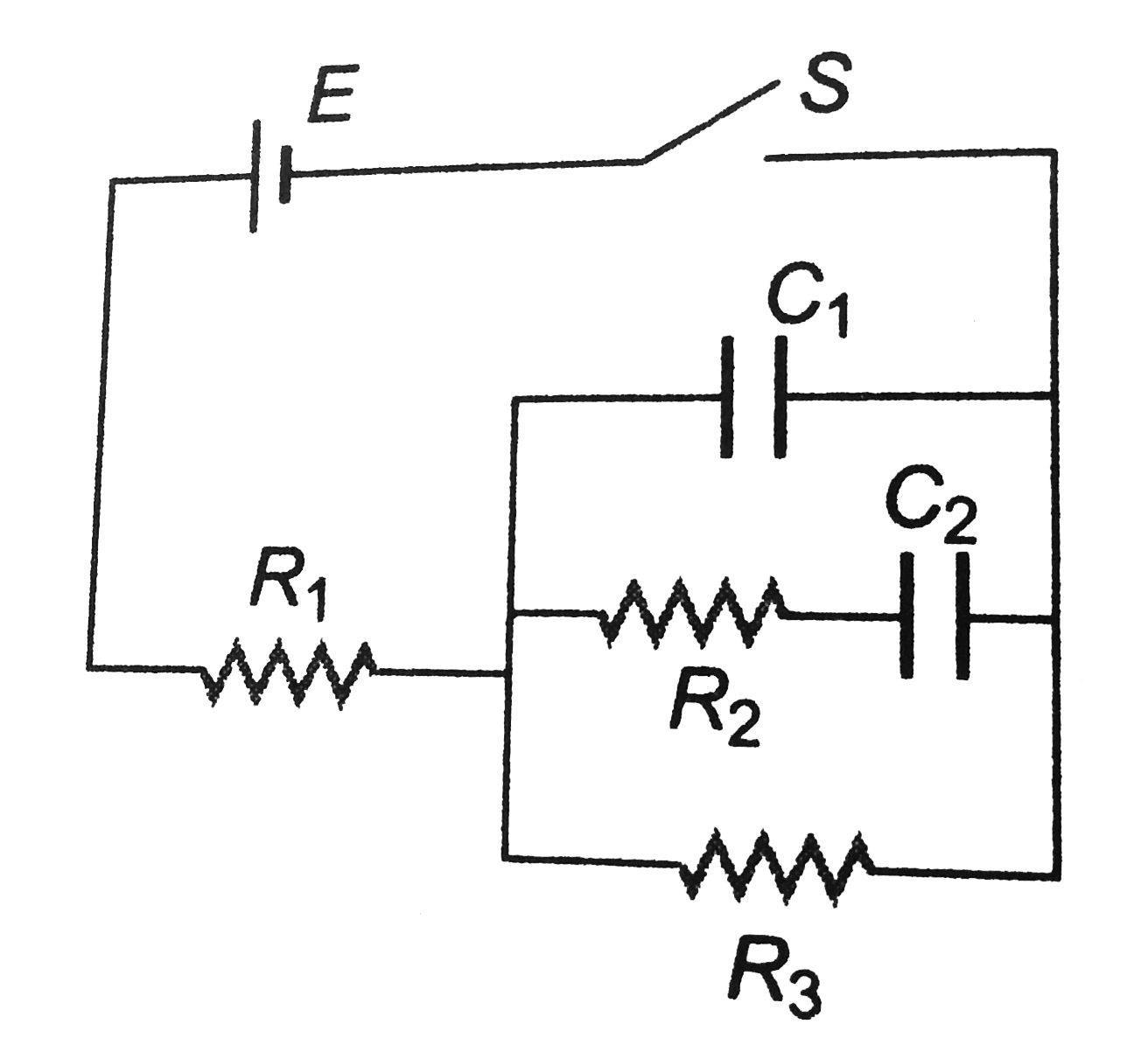
View SolutionIn the circuit shown initially C1,C2 are uncharged. After closing the switch

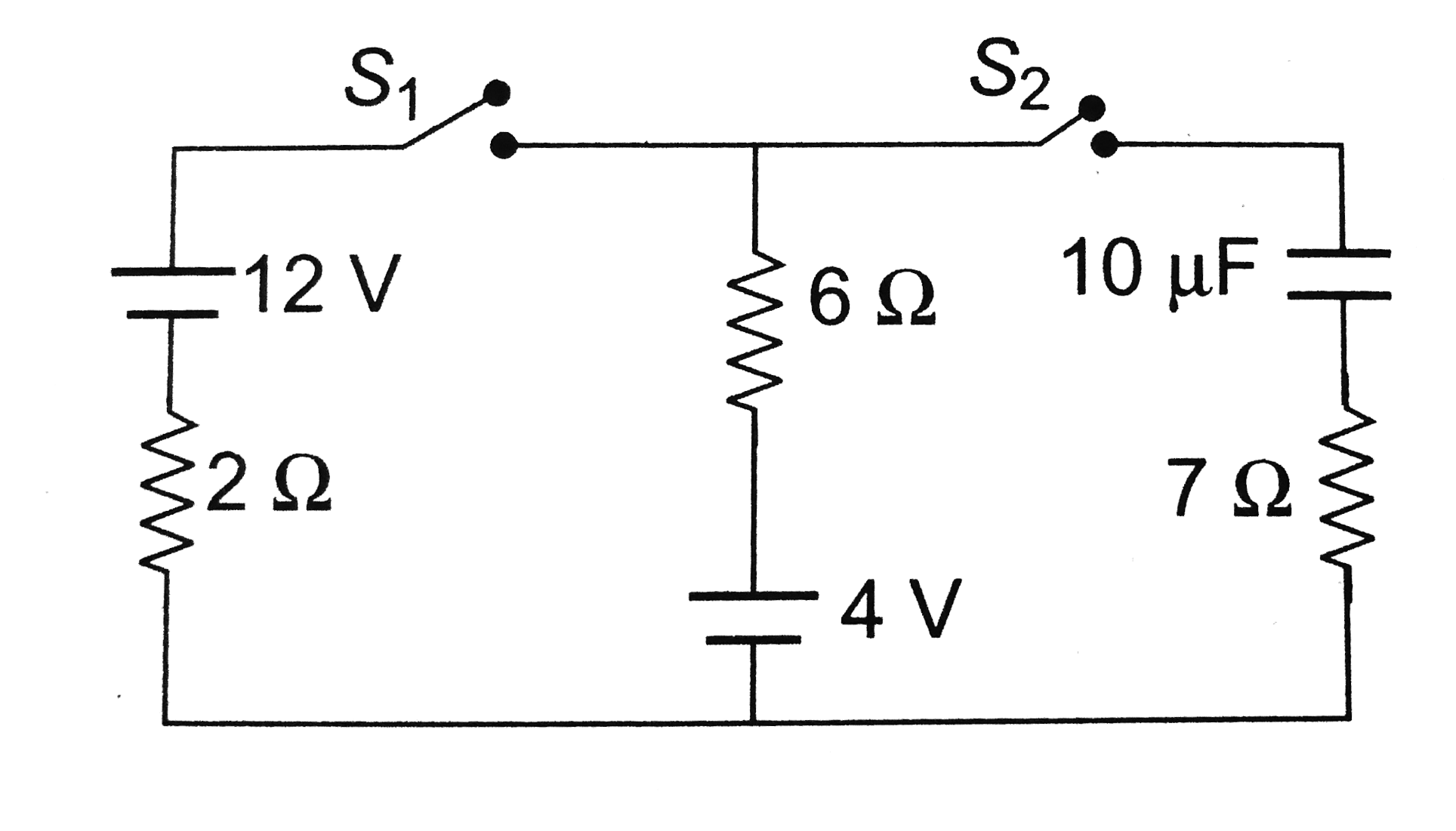
View SolutionIn the circuit shown in the figure, if switches S1 and S2 have been closed for a long time, then charge on the capacitor.
View SolutionConsider the circuit shown in figure. The current through the battery a long time after the switch S is closed is:

View SolutionIn the circuit shown in figure C1=2C2, Switch S is closed at time t = 0, Let i1andi2 be the currents flowing through C1andC2 at any time t, then the ratio i1/i2
View SolutionIn the circuit shown in figure, E=120V,R1=30.0Ω,R2=50.0Ω and L=0.200H. Switch S is closed at t=0. Just after the switch is closed.
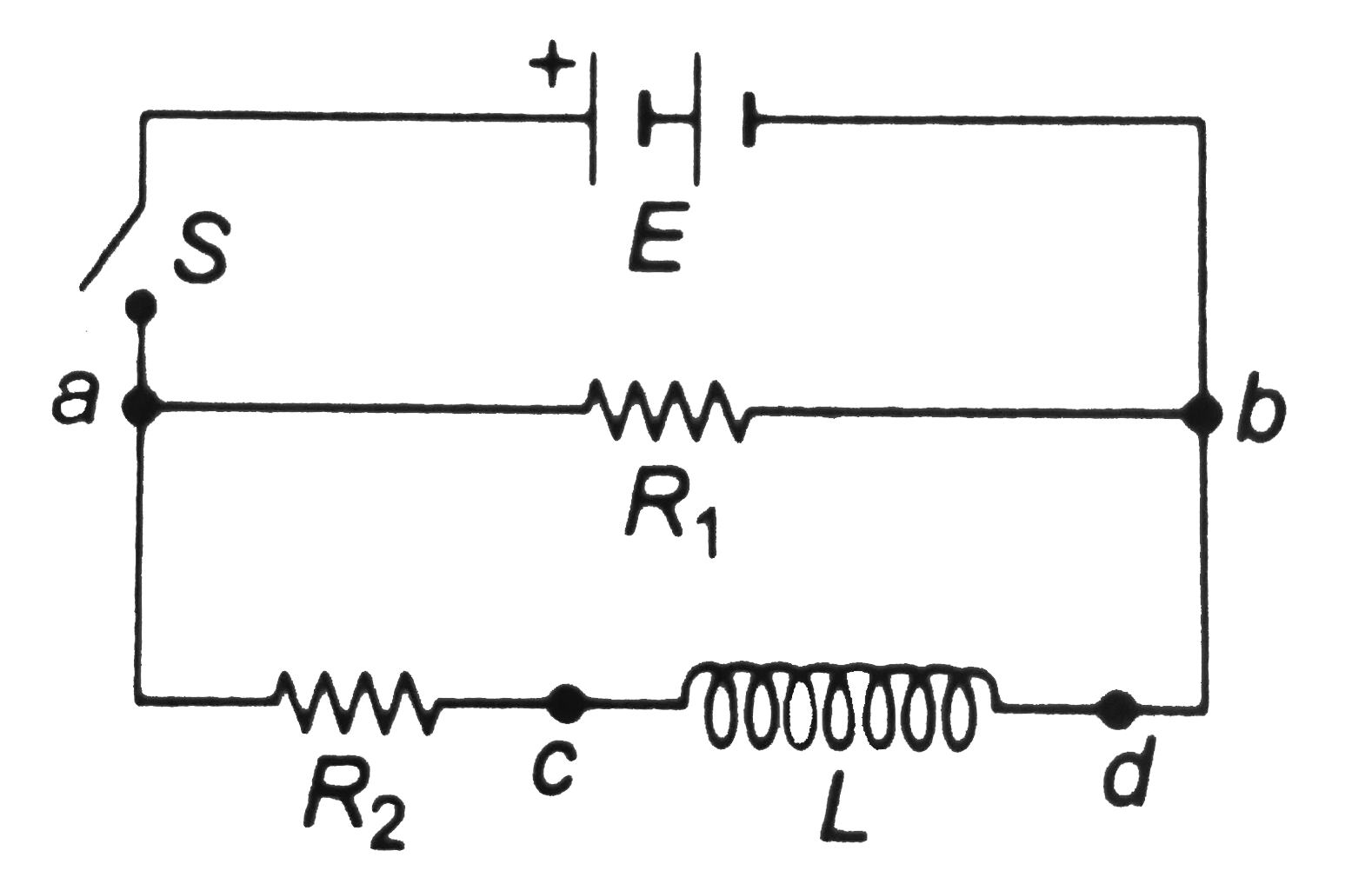
(a) What is the potential difference Vab across the inductor R1?
(b) Which point, a or b, is at higher potential?
(c) What is the potential difference Vcd across the inductor L?
(d) Which point, c or d, is at a higher potential? The switch is left closed for a long time and then is opened. Just after the switch is opened
(e) What is the potential difference Vab across the resistor R1?
(f) Which point a or b, is at a higher potential?
(g) What is the potential difference Vcd across the inductor L?
(h) Which point, c or d, is at a higher potential?
View Solution
