In the circuit shown in figure, E=120V,R1=30.0Ω,R2=50.0Ω and L=0.200H. Switch S is closed at t=0. Just after the switch is closed.
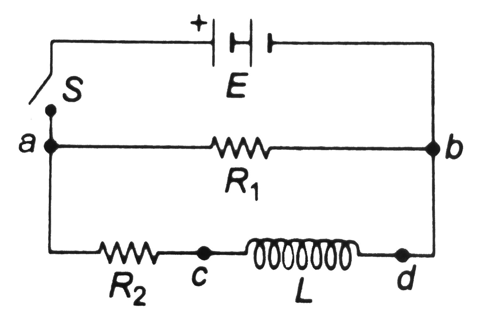
(a) What is the potential difference Vab across the inductor R1?
(b) Which point, a or b, is at higher potential?
(c) What is the potential difference Vcd across the inductor L?
(d) Which point, c or d, is at a higher potential? The switch is left closed for a long time and then is opened. Just after the switch is opened
(e) What is the potential difference Vab across the resistor R1?
(f) Which point a or b, is at a higher potential?
(g) What is the potential difference Vcd across the inductor L?
(h) Which point, c or d, is at a higher potential?
The correct Answer is:D
These are two independent parallel circuits across the battery.
a. Vab=E=120 volt (at all instants)
b.a is higher potential.
c. Vcd will decrease exponentially from 120V to zero.
∴Vcd=120volt, just after the switch is closed.
d. c will be at higher potential.
e. When switch is opeed, current through R1 will immediately become zero. While through R2, will decrease to zero from the value
ER2=2.4A=i0 (say), exponentially. Path of this decay of current will be cdbac.
∴ Just after the switch is opened.
Vab=−i0R1=−2.4×30=−72vo<
f. Point b is at higher potential.
g. Vcd=−i0(R1+R2)=−2.4(80)=−192volt
h. This time point d will be at higher potential.
Topper's Solved these Questions
- ELECTROMAGNETIC INDUCTIONBOOK - DC PANDEY ENGLISHCHAPTER - ELECTROMAGNETIC INDUCTIONEXERCISE - Example
71 Videos
- ELECTROMAGNETIC INDUCTIONBOOK - DC PANDEY ENGLISHCHAPTER - ELECTROMAGNETIC INDUCTIONEXERCISE - Check point
60 Videos
- ELECTROMAGNETIC INDUCTIONBOOK - DC PANDEY ENGLISHCHAPTER - ELECTROMAGNETIC INDUCTIONEXERCISE - SUBJECTIVE TYPE
1 Videos
- CURRENT ELECTRICITYBOOK - DC PANDEY ENGLISHCHAPTER - CURRENT ELECTRICITYEXERCISE - Medical entrances gallery
97 Videos
- ELECTROMAGNETIC WAVESBOOK - DC PANDEY ENGLISHCHAPTER - ELECTROMAGNETIC WAVESEXERCISE - Sec C
22 Videos
Similar Questions
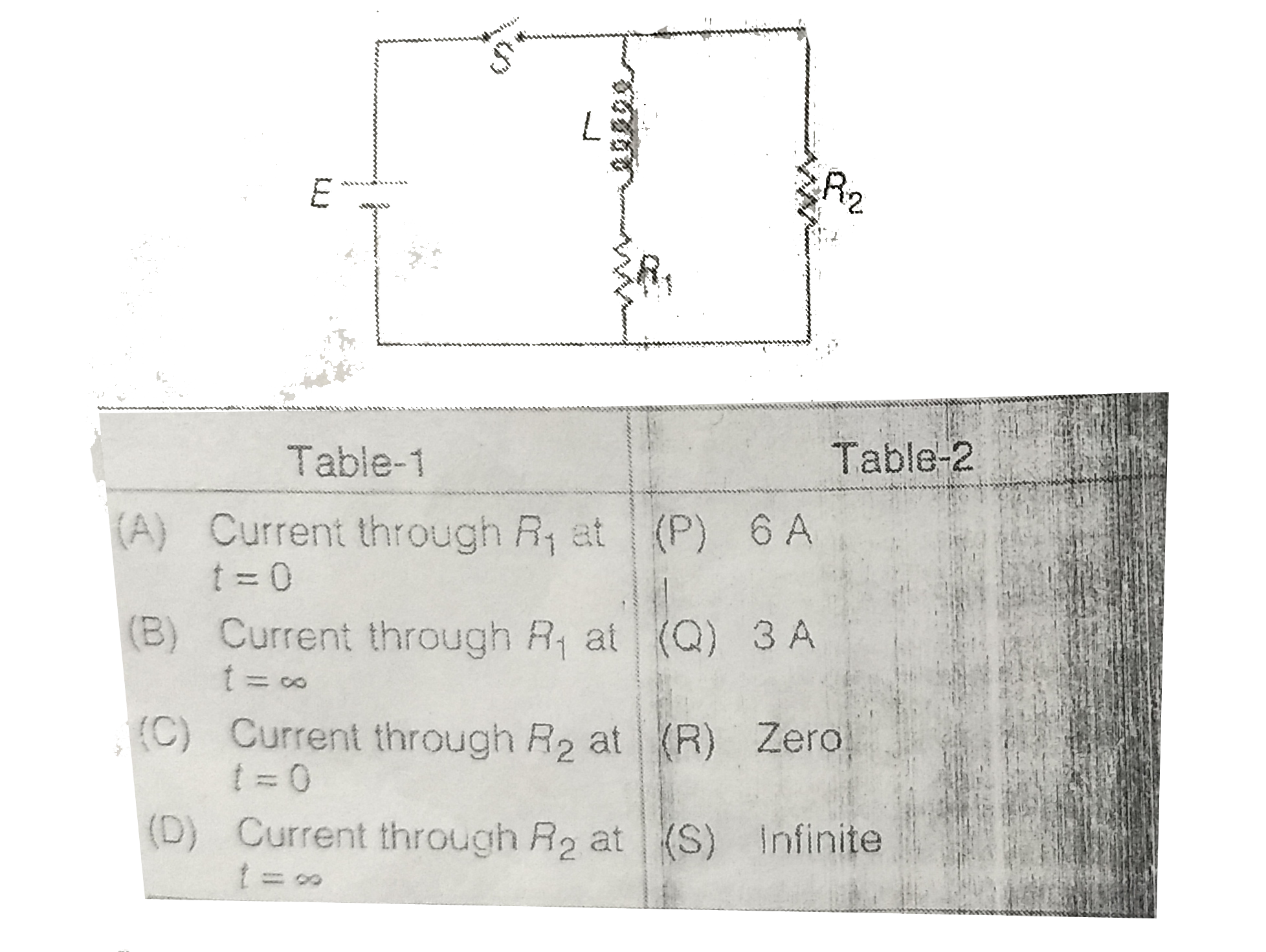
In the circuit diagram shown in Figure E=18V , L=2H, R1=3Ω,R2=6Ω. Switch S is closed at t=0 Match the following:
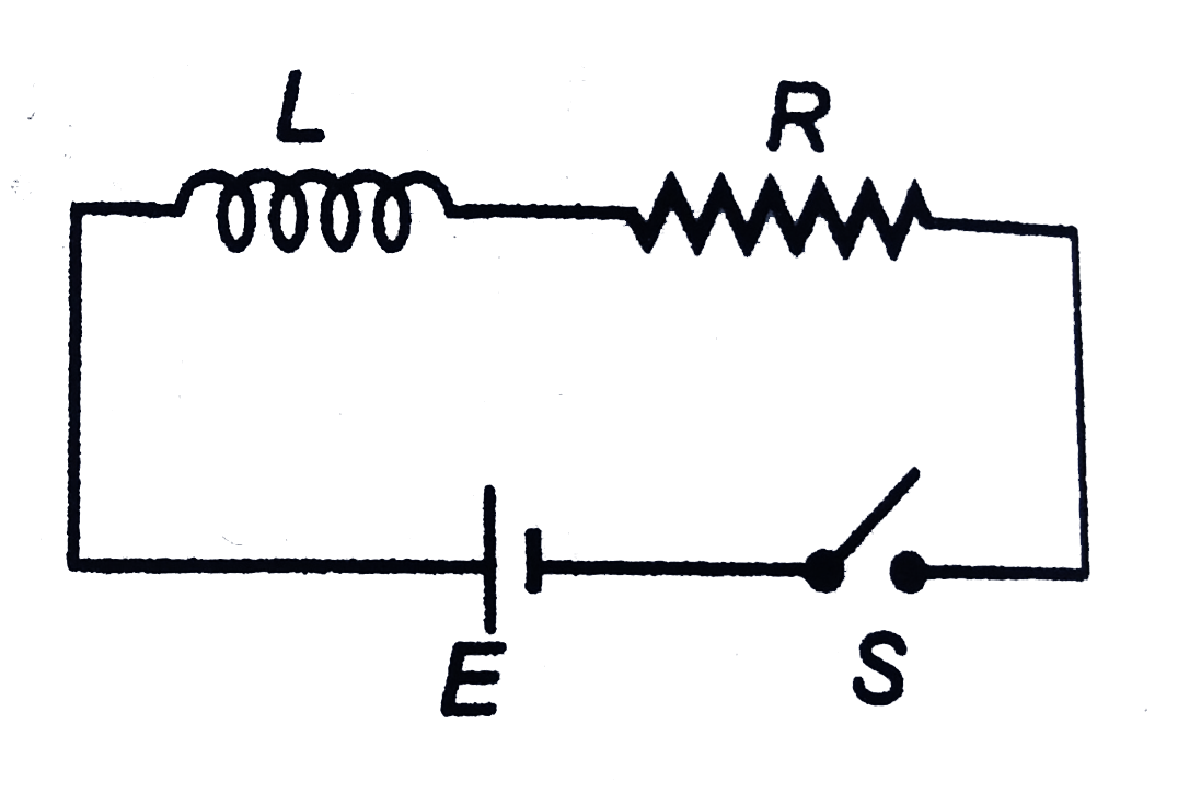
View SolutionIn the circuit shown in figure L=10H,R=5Ω,E=15V. The switch S is closed at t=0. At t=2s the current in the circuit is
View SolutionSwitch is closed at t=0 then the current in the circuit at t=L2R is
_PHY_E06_157_Q01.png)
View SolutionIn the circuit shown in fig, switch S was closed for long time. At time t-0, the switch is opened again. The maximum potential difference across the plates of the capacitor after the switch is opened is

View SolutionIn the circuit shown in figure

E1=10V,E2=4V,r1=r2=1Ω and R=2Ω.
Find the potential difference across battery 1 and battery 2.
View SolutionIn the circuit shown in figure

E1=10V,E2=4V,r1=r2=1Ω and R=2Ω.
Find the potential difference across battery 1 and battery 2.
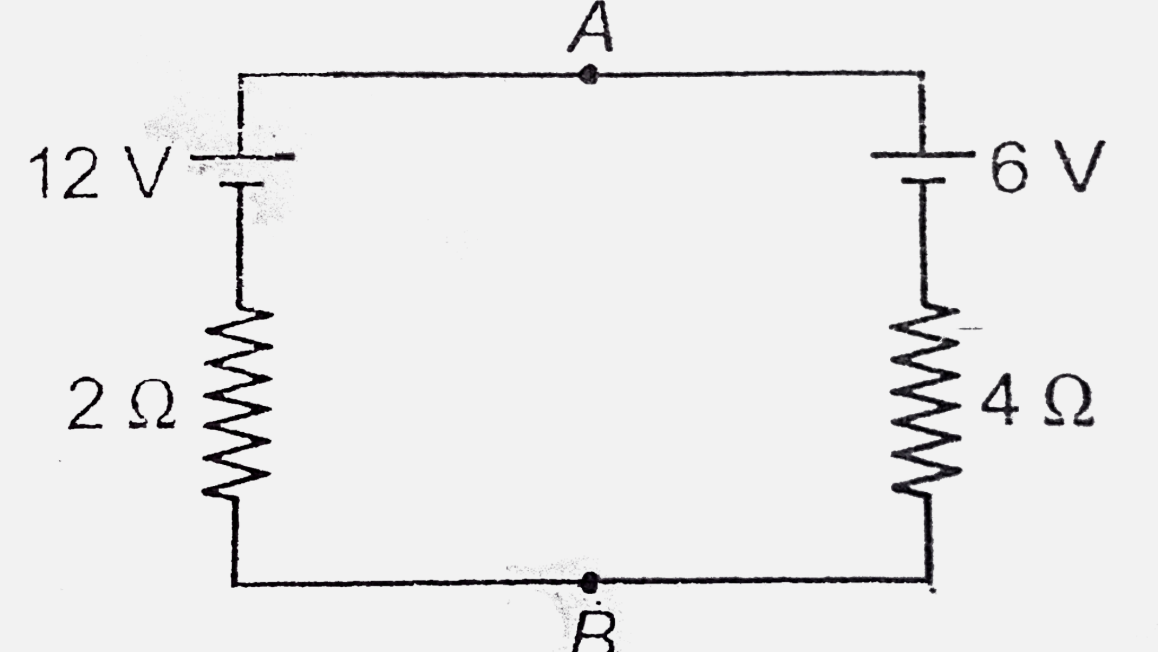
View SolutionPotential difference across AB , i.e., VA−VB is
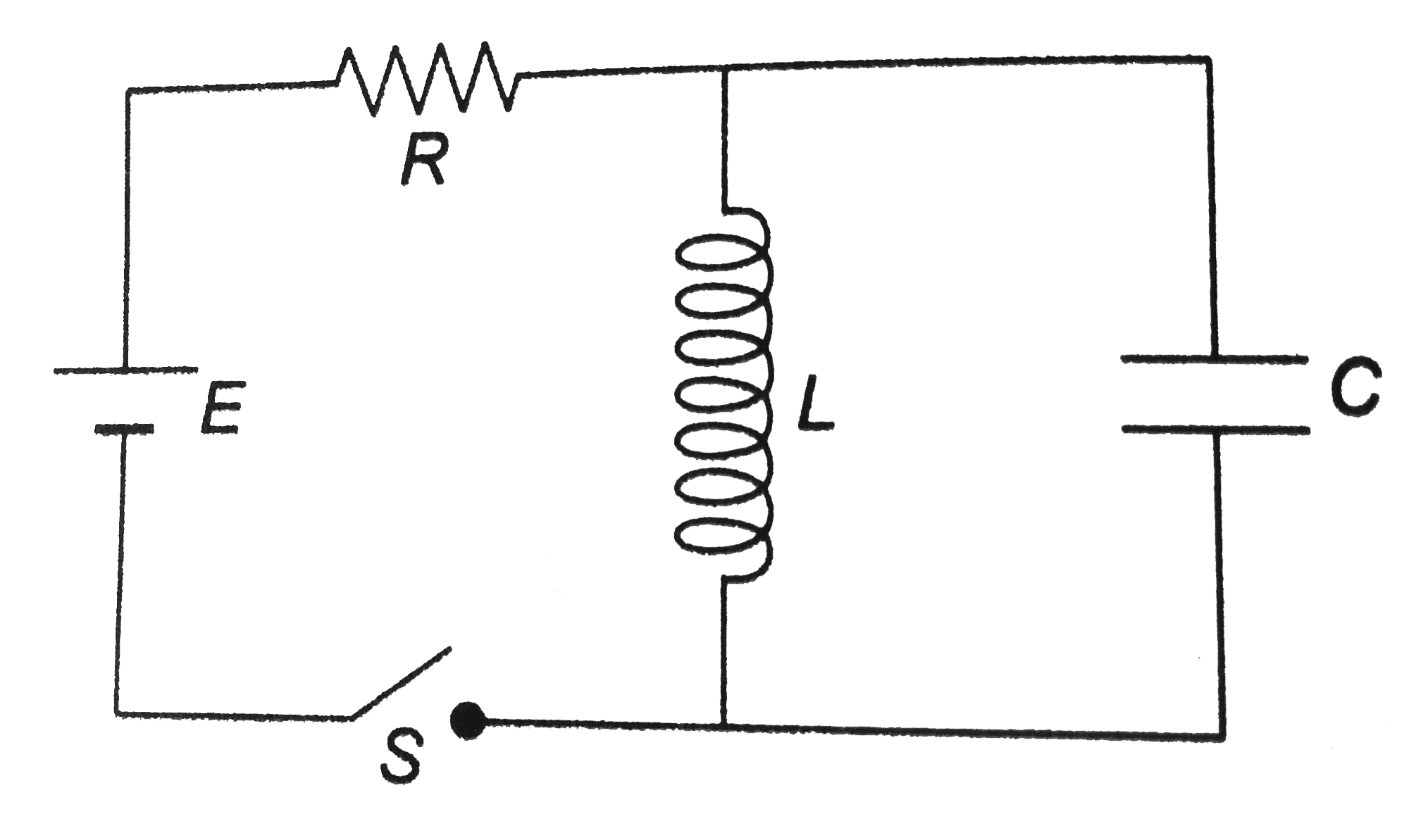
View SolutionIn the circuit shown in the figure, E=50.0V,R=250Ω and C=0.500μF. The switch S is closed for a long time, and no voltage is measured across the capacitor. After the switch is opened, the voltage across the capacitor reaches a maximum value of 150V. What is the inductance L?
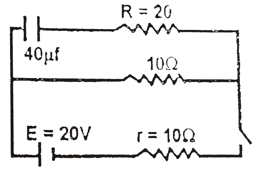
View SolutionIn the figure shown, the switch is closed at t=0. The potential difference across the resistance R=20Ω, 1 millisecond after closing the switch is K/e. Find the value of K.
View Solutionin a series LCR circuit, what is the phase difference between VLandVC where VL is the potential difference across the inductor and VC is the potential difference across the capacitor?
View Solution
