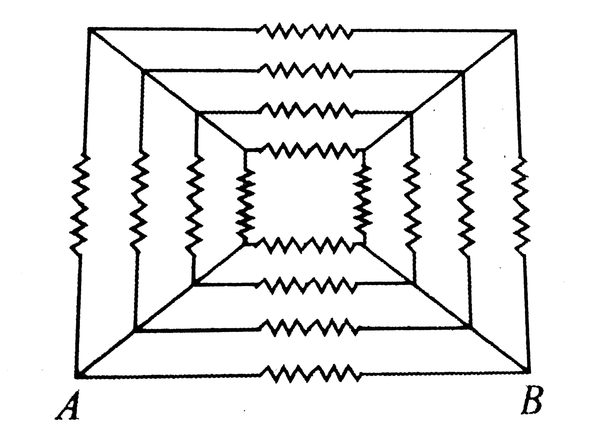
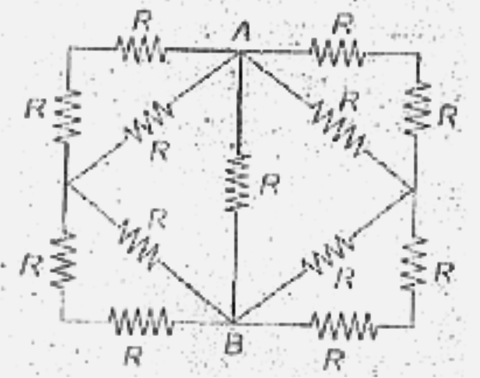
Sixteen resistor, each resistane 16Ω are connected in the circuit as shown in fig. the net resistance between A and B is
1Ω
2Ω
3Ω
Ω
The correct Answer is:C
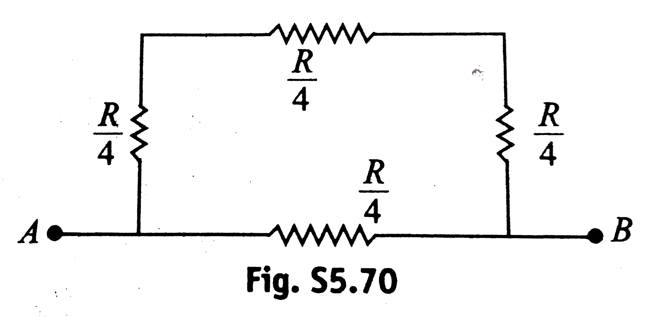
RAB=3R16=3(16)16=3Ω
Topper's Solved these Questions
- ELECTRIC CURRENT AND CIRCUITBOOK - CENGAGE PHYSICS ENGLISHCHAPTER - ELECTRIC CURRENT AND CIRCUITEXERCISE - Multiple Correct
16 Videos
- ELECTRIC CURRENT AND CIRCUITBOOK - CENGAGE PHYSICS ENGLISHCHAPTER - ELECTRIC CURRENT AND CIRCUITEXERCISE - Comprehension
35 Videos
- ELECTRIC CURRENT AND CIRCUITBOOK - CENGAGE PHYSICS ENGLISHCHAPTER - ELECTRIC CURRENT AND CIRCUITEXERCISE - Subjective
29 Videos
- ELECTRIC CURRENT & CIRCUITSBOOK - CENGAGE PHYSICS ENGLISHCHAPTER - ELECTRIC CURRENT & CIRCUITSEXERCISE - Kirchhoff s law and simple circuits
15 Videos
- ELECTRIC FLUX AND GAUSS LAWBOOK - CENGAGE PHYSICS ENGLISHCHAPTER - ELECTRIC FLUX AND GAUSS LAWEXERCISE - MCQ s
38 Videos
Similar Questions
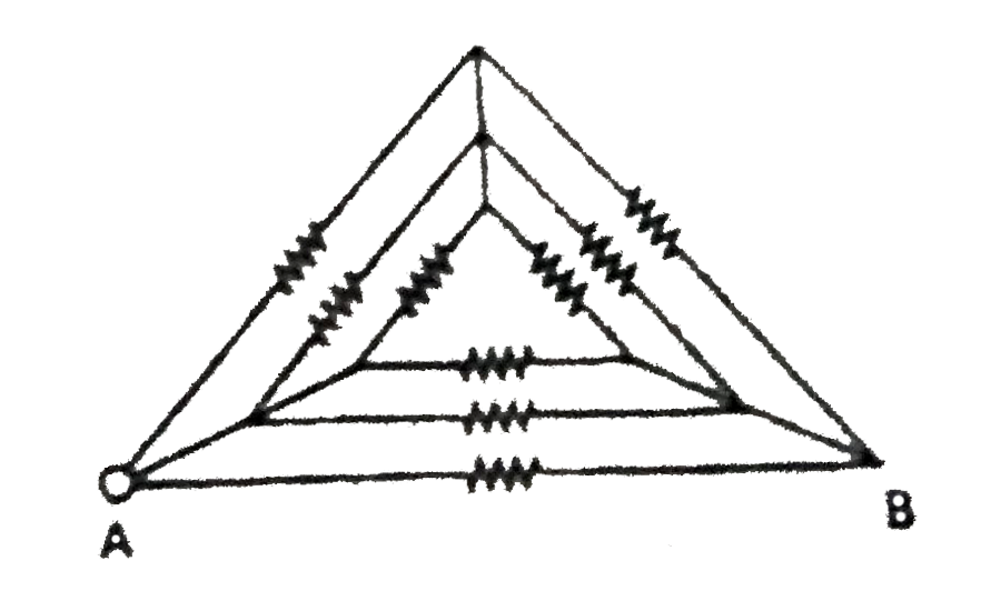
Nine resistors each of resistance R are connected in the circuit as shown in fig. The net resistance between A and B is
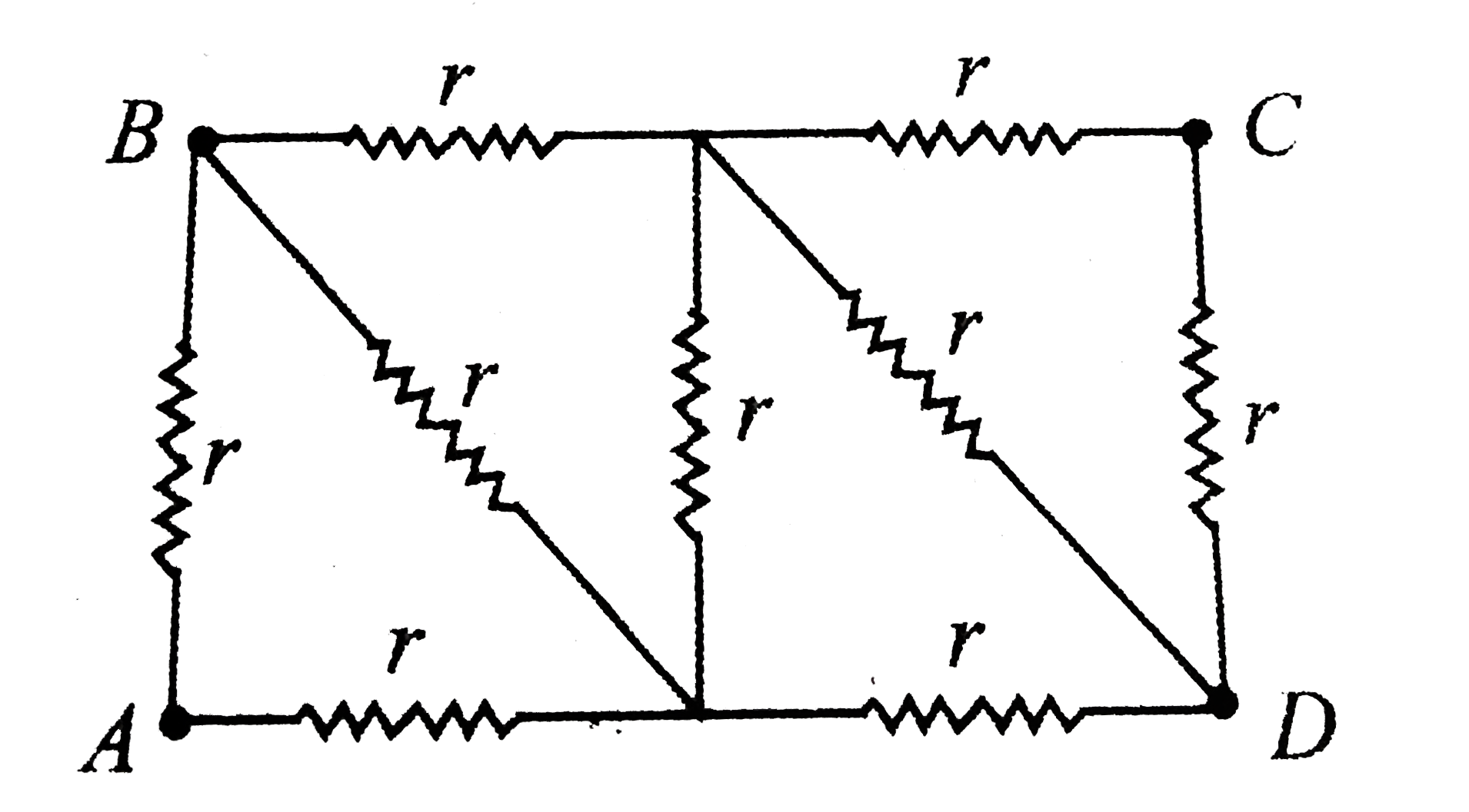
View SolutionFor the circuit shown in fig. the equivalent resistance between A and C is
View SolutionThirteen resistors each of resistance R are connected in the circuit as shown . The effective resistance between A and B is
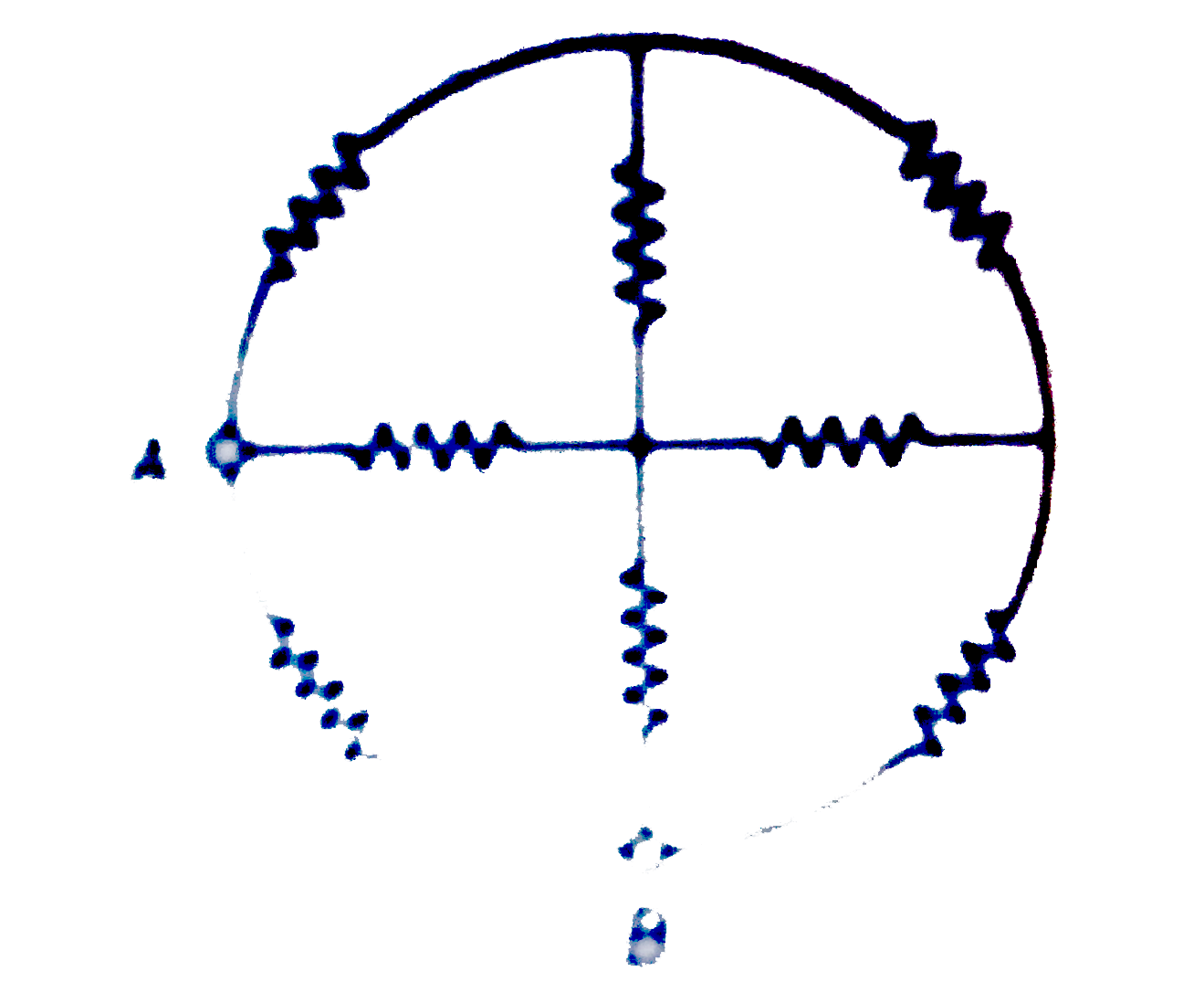
View SolutionEight resistances each of resistance 5Ω are connected in the circuit as shown in figure. The equivalent resistance between A and B is
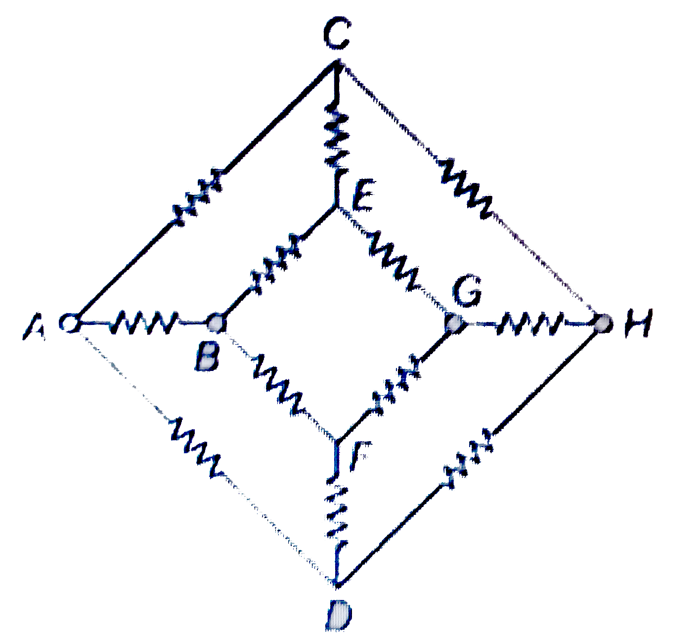
View SolutionTwelve resistors each of resistance 1Ω are connected in the circuit shown in figure. Net resistance between point A and H would be
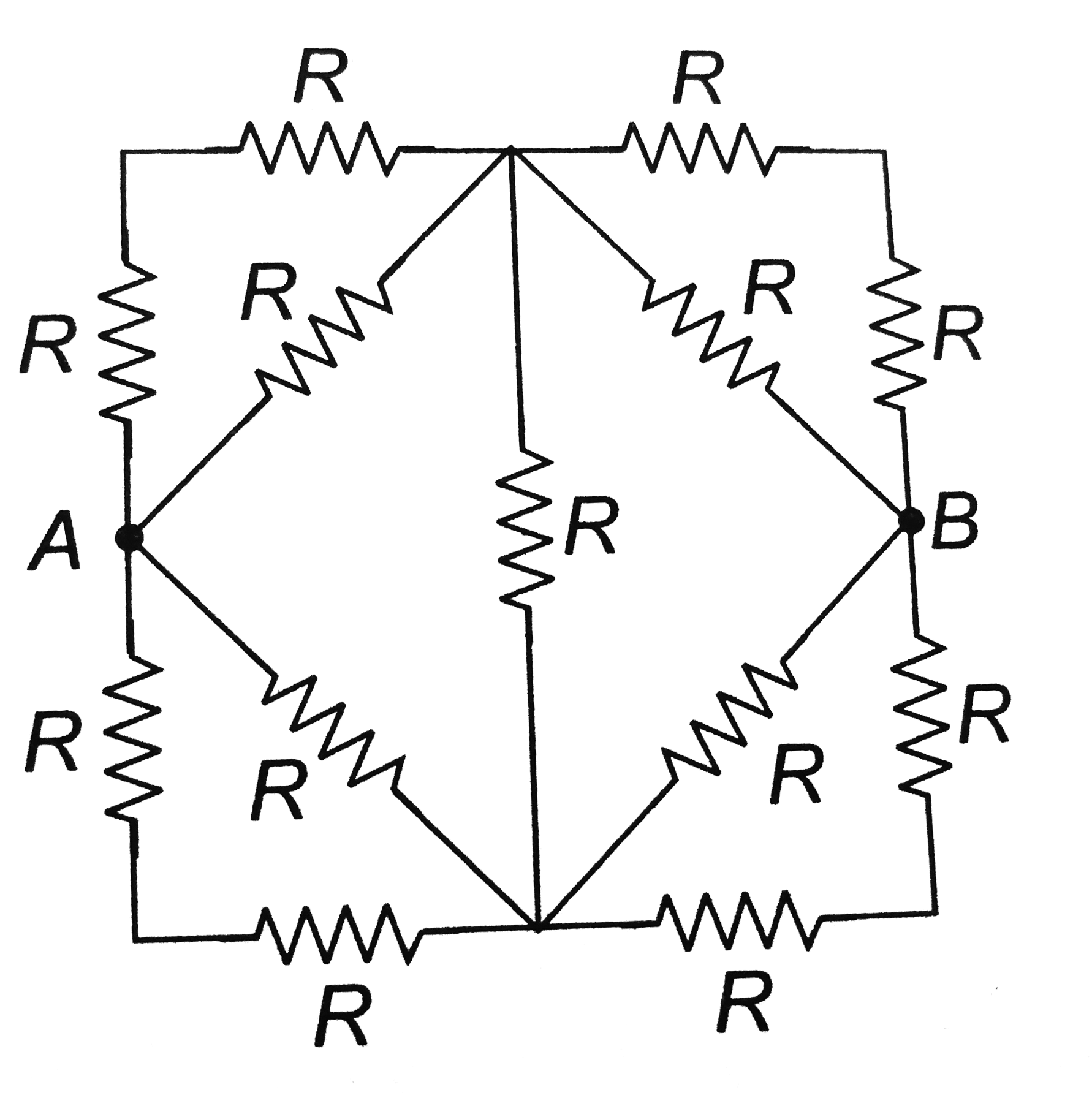
View SolutionThirteen resistances each of resistance R ohm are connected in the circuit as shown in the figure below. The effective resistance between A and B is
View SolutionThirteen resistances each of resistance R ohm are connected in the circuit as shown in the figure below. The effective resistance between A and B is

View SolutionThirteen resistances each of resistance R ohm are connected in the circuit as shown in the figure below. The effective resistance between A and B is

View SolutionFour equal resistors, each of resistance 10Ω, are connected as shown in the circuit diagram. The equivalent resistance between A and B is
View SolutionIn the circuit shown in figure, the equivalent resistance between A and B is __________ Ω.
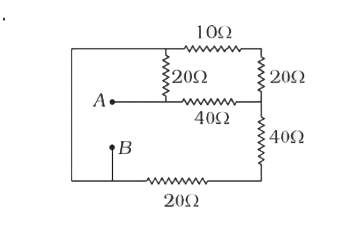
View Solution
