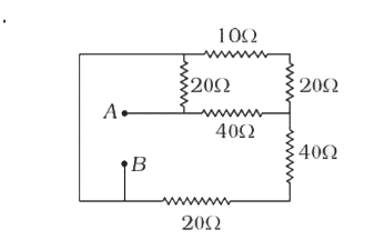
In the circuit shown in figure, the equivalent resistance between A and B is __________ Ω.
Video Solution
Text Solution
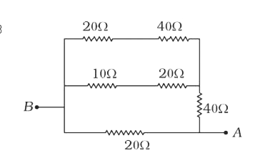
Equivalent circuit diagram of the circuit is
SO Req=15Ω
|
Topper's Solved these Questions
- DC CIRCUITBOOK - VMC MODULES ENGLISHCHAPTER - DC CIRCUITEXERCISE - LEVEL-2 DAILY TUTORIAL SHEET-1
10 Videos
- DC CIRCUITBOOK - VMC MODULES ENGLISHCHAPTER - DC CIRCUITEXERCISE - LEVEL-2 DAILY TUTORIAL SHEET-2
10 Videos
- DC CIRCUITBOOK - VMC MODULES ENGLISHCHAPTER - DC CIRCUITEXERCISE - LEVEL-1 DAILY TUTORIAL SHEET-4
15 Videos
- CURRENT ELECTRICITYBOOK - VMC MODULES ENGLISHCHAPTER - CURRENT ELECTRICITYEXERCISE - IN-CHAPTER EXERCISE-F
10 Videos
- DYNAMICS OF A PARTICLEBOOK - VMC MODULES ENGLISHCHAPTER - DYNAMICS OF A PARTICLEEXERCISE - JEE Advance (Archive) Level - II (SINGLE OPTION CORRECT TYPE )
31 Videos
Similar Questions
Knowledge Check
The circuit as shown in the figure is equivalent to
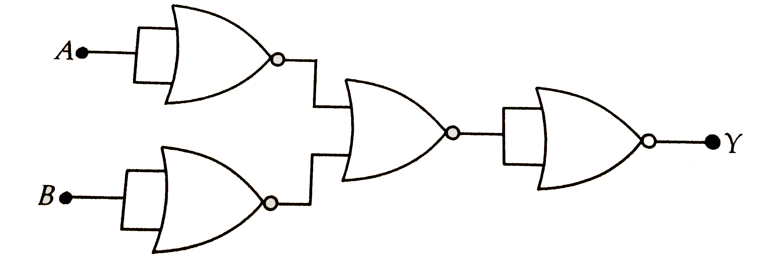 AAND gateBNOT gateCOR gateDNAND gate
In the network shown in the figure, the equivalent resistance between A and C is
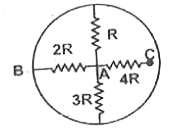
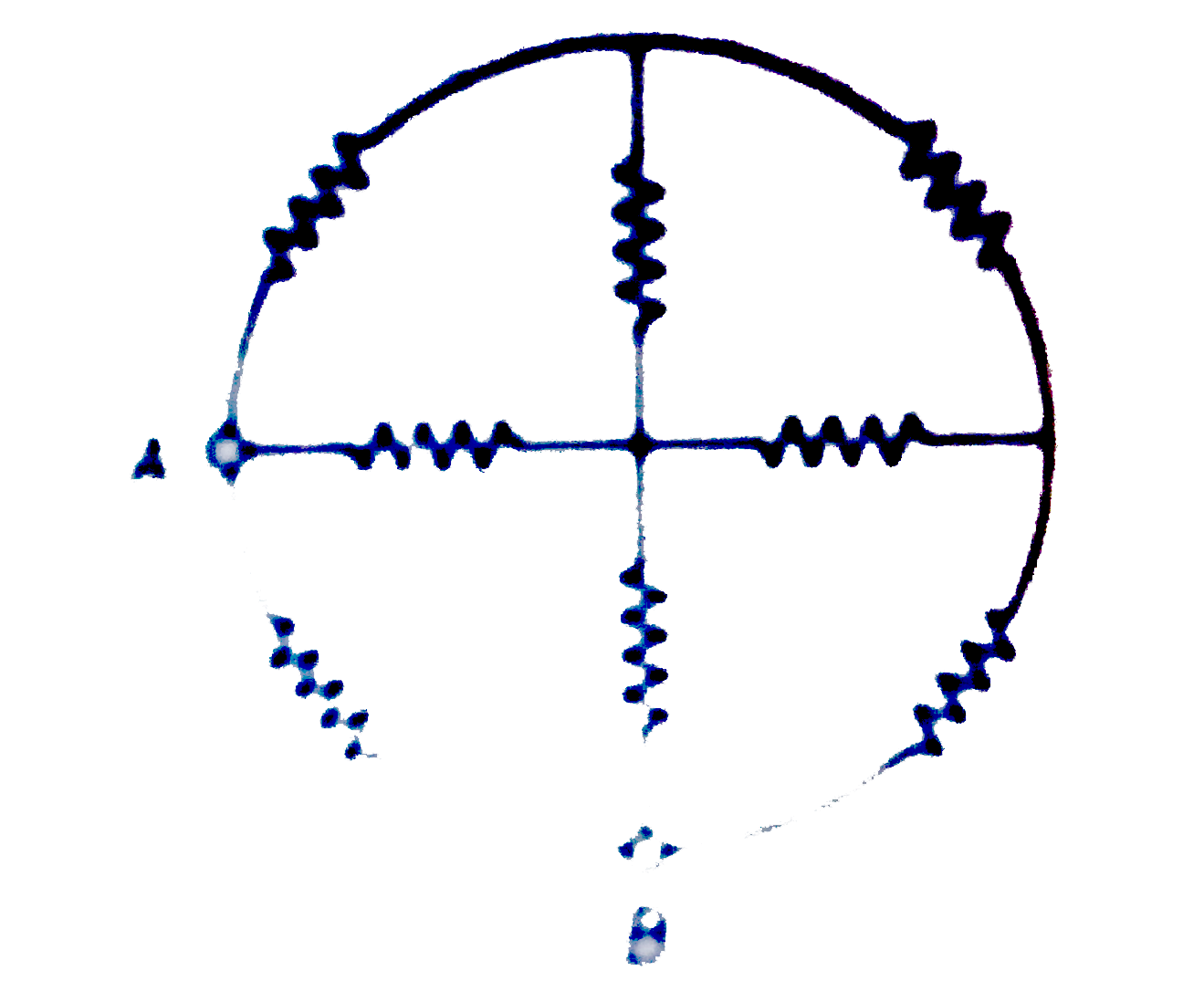
View SolutionEight resistances each of resistance 5Ω are connected in the circuit as shown in figure. The equivalent resistance between A and B is
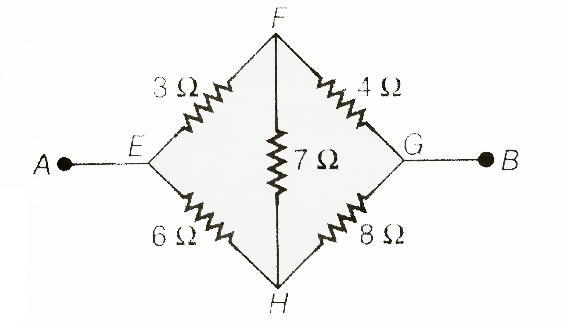
View SolutionA bridge circuit is shown in figure. The equivalent resistance between A and B will be
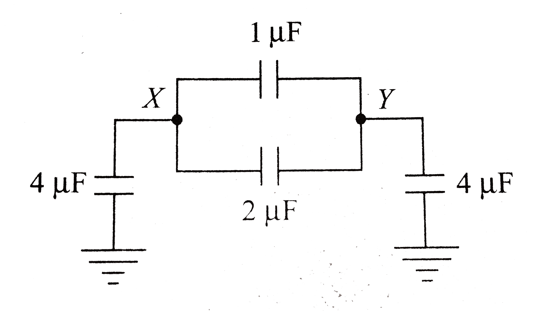
View SolutionIn the circuit shown in figure, the equivalent capacitance between the points X and Y is
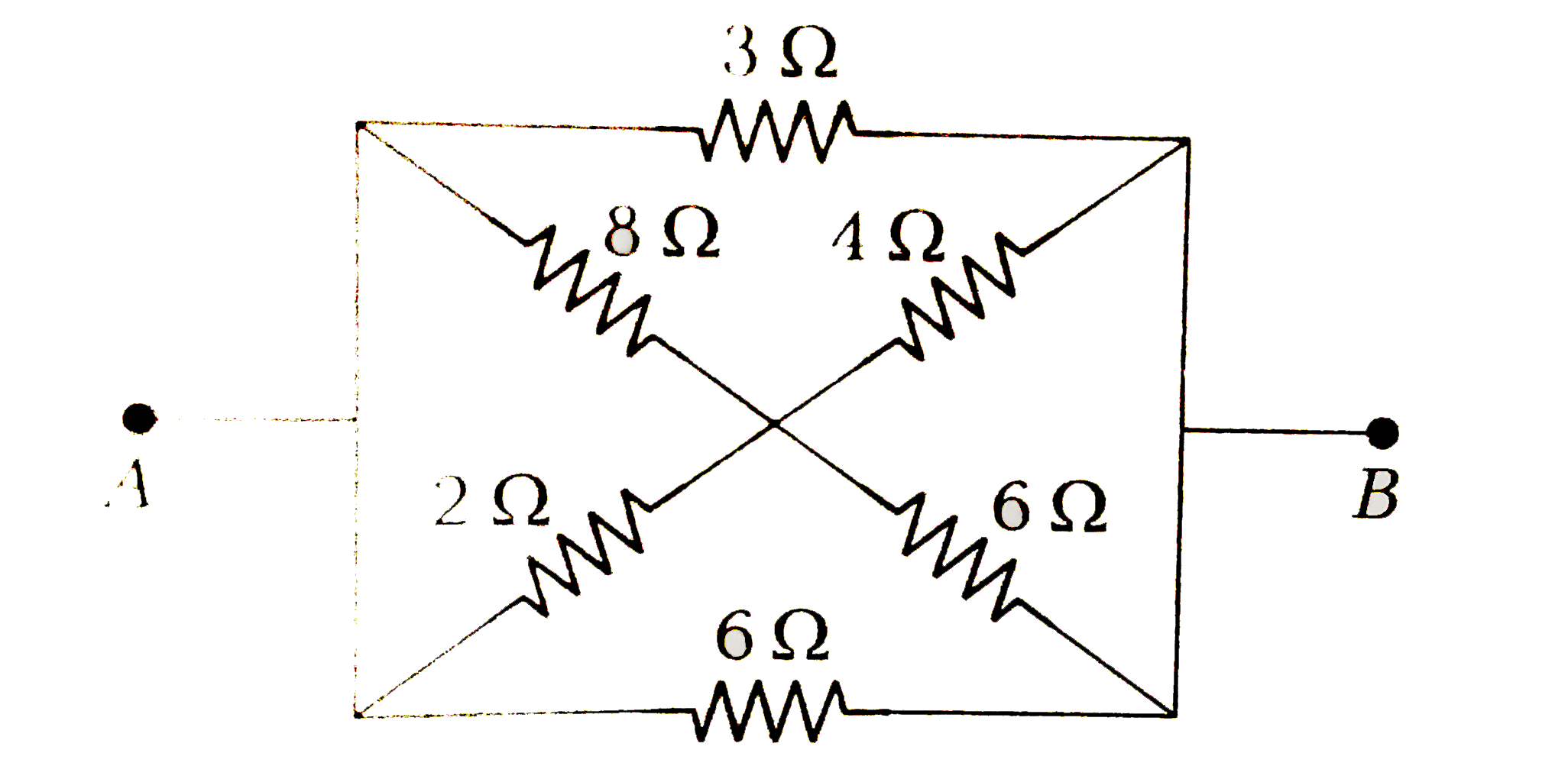
View SolutionIn the network shown, the equivalent resistance between A and B is
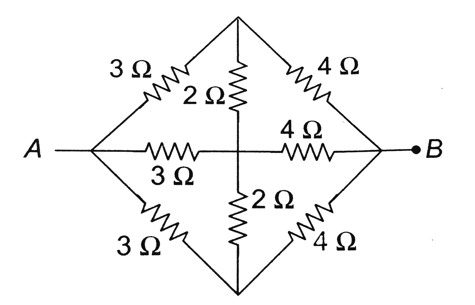
View SolutionThe equivalent resistance between A and B will be (in Ω)
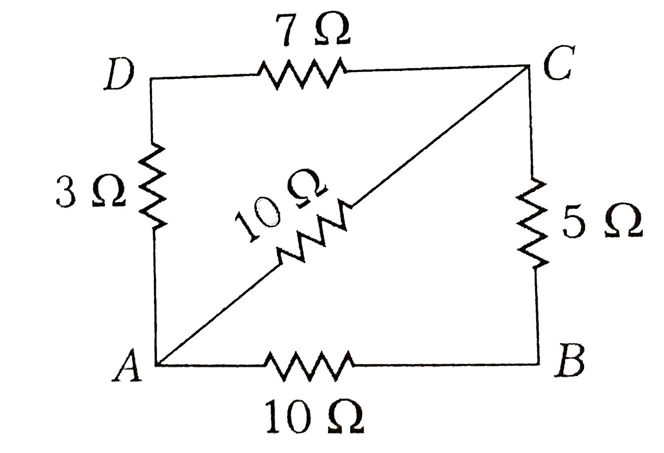
View SolutionFor the circuit shown in figure given below, the equivalent resistance points A and B is
View Solution

