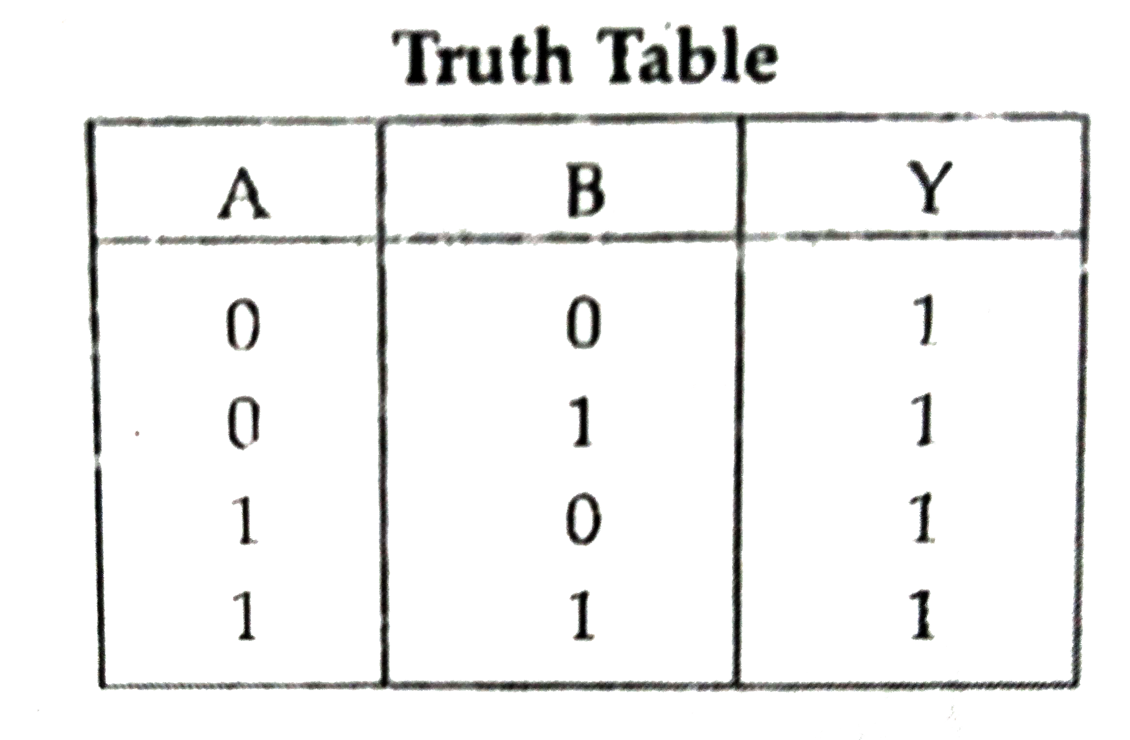
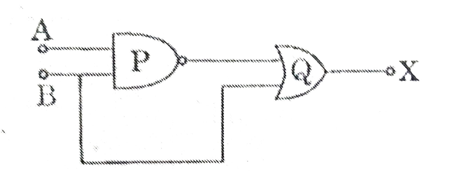
Identify the logic gates marked P and Q in the circuit Fig. Write the truth table for this combination.

P gate = NAND
Q gate = OR
Topper's Solved these Questions
- XII BOARDSBOOK - XII BOARD PREVIOUS YEAR PAPER ENGLISHCHAPTER - XII BOARDSEXERCISE - [SET - II DELHI BOARD]
5 Videos
- XII BOARDSBOOK - XII BOARD PREVIOUS YEAR PAPER ENGLISHCHAPTER - XII BOARDSEXERCISE - [SET - III, DELHI BOARD]
6 Videos
- XII BOARDSBOOK - XII BOARD PREVIOUS YEAR PAPER ENGLISHCHAPTER - XII BOARDSEXERCISE - SET-II
33 Videos
- SAMPLE PAPER 2019BOOK - XII BOARD PREVIOUS YEAR PAPER ENGLISHCHAPTER - SAMPLE PAPER 2019EXERCISE - SECTION D
6 Videos
Similar Questions
Identify the gates P and Q shown in the figure. Write the truth table for the combination of the gates shown.

Name the equivalent gate representing this circuit and write its logic symbol.
View Solution(i) Identify the logic gates marked P and Q in the given logic circuit Fig.

(ii) Write down the output at X for the inputs A=0,B=0 and A=1,B=1.
View Solution(i) Identify the logic gates marked P and Q in the given logic circuit.
(ii) Write down the output at X for the inputs A = 0 , B = 0 and A = 1 , B = 1.
View SolutionGive the truth table of ~p∨q
View SolutionFor the logic circuit shown the truth table is

View SolutionConstruct the truth table for p∧q.
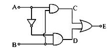
View SolutionTruth table for the given circuit is
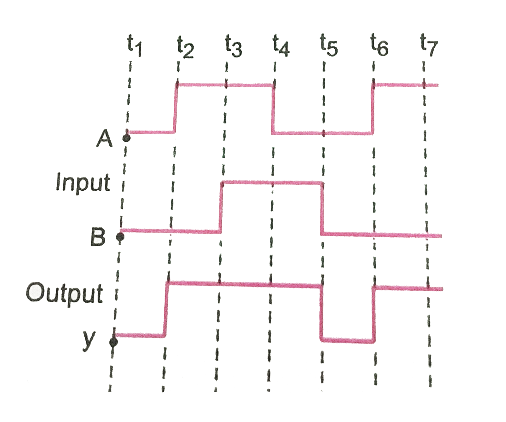
View SolutionThe Fig shown input waveforms A and B to a logic gate. Draw the output waveform for an OR gate. Write the truth table for this logic gate and draw its logic symbol.
View SolutionFor given logic gate truth table is
View SolutionThe truth table for the following combination of gates is :-
_E01_430_Q01.png)
View Solution
