Draw a schematic sketch of an generator describing its basic elements. State briefly its working principle. Show a plot of variation of
(i) Magnetic flux and
(ii) Alternating emf versus time generated by a loop of wire rotating in a magnetic field.
(b) Why is choke coil needed in the use of fluorescent tubes with ac mains?
Step-by-Step Solution
1. Draw the Schematic Sketch:
- Begin by sketching a rectangular coil labeled ABCD.
- Add two strong electromagnets, one labeled North (N) and the other South (S), positioned around the coil.
- Include two slip rings (R1 and R2) connected to the ends of the coil.
- Add two brushes (B1 and B2) that make contact with the slip rings.
Diagram:
N||||∣||||||||∣||||S−−−−−−|∣|ABCD∣−−−−−−B1B2R1R2
2. Identify Basic Elements:
- Armature: The rectangular coil ABCD is known as the armature.
- Field Magnets: The strong electromagnets (N and S) create a magnetic field.
- Slip Rings: R1 and R2 allow the current to flow out of the coil.
- Brushes: B1 and B2 maintain contact with the slip rings to transfer current.
3. State the Working Principle:
- As the coil rotates in the magnetic field, the angle (θ) between the magnetic field and the normal to the coil changes continuously.
- According to Faraday's law of electromagnetic induction, a change in magnetic flux linked with the coil induces an electromotive force (EMF).
- The induced EMF is alternating in nature due to the continuous change in angle θ, causing the current to alternate direction.
4. Plot the Variation of Magnetic Flux and EMF:
- Magnetic Flux (Φ): The magnetic flux linked with the coil can be expressed as:
\(
Φ = NBA \cos(θ) = NBA \cos(ωt)
\)
- Graph of Magnetic Flux vs. Time: The graph will be a cosine wave, oscillating between maximum and minimum values.
- Induced EMF (E): The induced EMF can be derived as:
\(
E = -\frac{dΦ}{dt} = N B A ω \sin(ωt)
\)
- Graph of EMF vs. Time: The graph will be a sine wave, oscillating between positive and negative maximum values.
Graphs:
- Magnetic Flux (Φ) vs. Time (t):
Φ∣∣
∣
∣∣|/|∣∣/⌊_______∣∣∣∣
∣
∣∣||∣||∣⎢⎢
⎢
⎢
⎢⎣_⎥⎥
⎥
⎥
⎥⎦__⌋___⎥⎥
⎥
⎥
⎥⎦__t
- Induced EMF (E) vs. Time (t):
E∣∣
∣
∣∣|/|∣∣/⌊_______∣∣∣∣
∣
∣∣||∣||∣⎢⎢
⎢
⎢
⎢⎣_⎥⎥
⎥
⎥
⎥⎦__⌋___⎥⎥
⎥
⎥
⎥⎦__t
Part (b): Choke Coil in Fluorescent Tubes with AC Mains
1. Explain the Need for a Choke Coil:
- A choke coil is used in fluorescent tubes to limit the current flowing through the tube.
- It provides the necessary voltage to start the tube and stabilizes the current during operation.
- Without a choke, the current would increase excessively, leading to overheating and potential damage to the tube.
2. Energy Efficiency:
- Using a choke coil prevents excessive energy loss that would occur if a simple resistor were used, which would dissipate energy as heat.
- Begin by sketching a rectangular coil labeled ABCD.
- Add two strong electromagnets, one labeled North (N) and the other South (S), positioned around the coil.
- Include two slip rings (R1 and R2) connected to the ends of the coil.
- Add two brushes (B1 and B2) that make contact with the slip rings.
N||||∣||||||||∣||||S−−−−−−|∣|ABCD∣−−−−−−B1B2R1R2
- Armature: The rectangular coil ABCD is known as the armature.
- Field Magnets: The strong electromagnets (N and S) create a magnetic field.
- Slip Rings: R1 and R2 allow the current to flow out of the coil.
- Brushes: B1 and B2 maintain contact with the slip rings to transfer current.
- As the coil rotates in the magnetic field, the angle (θ) between the magnetic field and the normal to the coil changes continuously.
- According to Faraday's law of electromagnetic induction, a change in magnetic flux linked with the coil induces an electromotive force (EMF).
- The induced EMF is alternating in nature due to the continuous change in angle θ, causing the current to alternate direction.
- Magnetic Flux (Φ): The magnetic flux linked with the coil can be expressed as:
\(
Φ = NBA \cos(θ) = NBA \cos(ωt)
\)
- Graph of Magnetic Flux vs. Time: The graph will be a cosine wave, oscillating between maximum and minimum values.
- Induced EMF (E): The induced EMF can be derived as:
\(
E = -\frac{dΦ}{dt} = N B A ω \sin(ωt)
\)
- Graph of EMF vs. Time: The graph will be a sine wave, oscillating between positive and negative maximum values.
- Magnetic Flux (Φ) vs. Time (t):
Φ∣∣
∣
∣∣|/|∣∣/⌊_______∣∣∣∣
∣
∣∣||∣||∣⎢⎢
⎢
⎢
⎢⎣_⎥⎥
⎥
⎥
⎥⎦__⌋___⎥⎥
⎥
⎥
⎥⎦__t
E∣∣
∣
∣∣|/|∣∣/⌊_______∣∣∣∣
∣
∣∣||∣||∣⎢⎢
⎢
⎢
⎢⎣_⎥⎥
⎥
⎥
⎥⎦__⌋___⎥⎥
⎥
⎥
⎥⎦__t
- A choke coil is used in fluorescent tubes to limit the current flowing through the tube.
- It provides the necessary voltage to start the tube and stabilizes the current during operation.
- Without a choke, the current would increase excessively, leading to overheating and potential damage to the tube.
- Using a choke coil prevents excessive energy loss that would occur if a simple resistor were used, which would dissipate energy as heat.
Topper's Solved these Questions
- XII BOARDSBook:XII BOARD PREVIOUS YEAR PAPER ENGLISHChapter:XII BOARDSExercise:[SET - II DELHI BOARD]
Explore 5 Videos
- XII BOARDSBook:XII BOARD PREVIOUS YEAR PAPER ENGLISHChapter:XII BOARDSExercise:[SET - III, DELHI BOARD]
Explore 6 Videos
- XII BOARDSBook:XII BOARD PREVIOUS YEAR PAPER ENGLISHChapter:XII BOARDSExercise:SET-II
Explore 33 Videos
- SAMPLE PAPER 2019Book:XII BOARD PREVIOUS YEAR PAPER ENGLISHChapter:SAMPLE PAPER 2019Exercise:SECTION D
Explore 6 Videos
Similar Questions
Describe briefly, with the help of a labell diagram, the basic elements of an A.C. generator. State its underlying principle. Show diagrammatically how an alternating emf is generated by a loop of wire rotating in a magnetic field. Write the expression for the instantaneous value of emf induced in the rotating loop.
View Solution(a) Draw a schematic diagram of an AC generator. Explain is working and obtain the expression for the instantaneous value of the emf in terms of the magnetic field B, number of turns N of the coil of area A rotating with angular frequency ω. Show how an alternating emf is generated by loop of wire rotating in a magnetic field.
(b) A circular coil of radius 10 cm and 20 turns is rotated about its vertical diameter with angular speed of 50 rad s−1. in a uniform horizontal magnetic field of 3.0×10⁻²T.
(i) Calculate the maximum and average emf induced in the coil.
(ii) If the coil forms a closed loop of resistance 10Ω, calculate the maximum current in the coil and the average power loss due to Joule heating.
View Solution(a) Describe a simple experiment (or activity) to show that the polarity of emf induced in a coil is always such that it tends to produce a current which opposes the change of magnetic flux that produces it.
(b) The current flowing through an inductor of self inductance L is continuously increasing. Plot a graph showing the variation of
(i) Magnetic flux versus the current
(ii) Induced emf versus dI/Dt
(iii) Magnetic potential energy stored versus the current.
View Solution(a) Draw a labelled diagrame of an ac generator. Obtain the expression for the emf induced
in the rotating coil of N turns each of cross-sectional are A, in the presence of a magnetic
field →B .
(b) A horizonatal conducting rod 10m long extending from east to west is falling with a
speed 5.0 ms ^(−1) at right angles to the horizontal component of the Earth's magnetic fields.
0.3×10⁻⁴Wbm−2. Find the instantaneous value of the emf induced in the rod .
View SolutionA square loop of edge b having M turns is rotated with a uniform angular velocity ω about one of its diagonals which is kept fixed in a horizontal position. A uniform magnetic field B0 exists in the vertical direction.
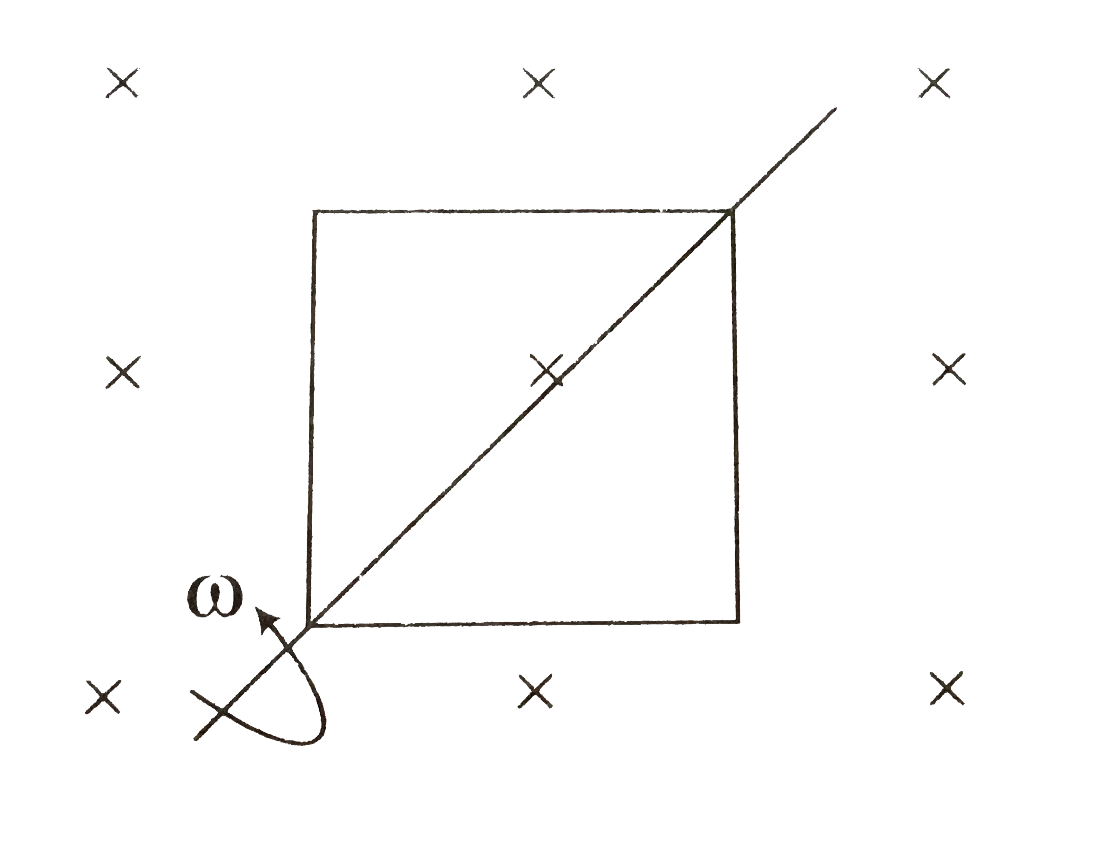
Find (i) the emf induced in the coil as a function of time t.
(ii) the maximum emf induced.
(iii) the average emf induced in the loop over a long period.
(iv) if resistance of loop is R, amount of charge flown in time t = 0 to t = 2T.
(v) heat produced in time t = 0 to t = 2T.
View SolutionA dc motor works on the principle that a current carrying coil, when placed in a magnetic field experiences a torque. The arrangement consists of a coil suspended in a region of magnetic field. When a current is passed through the coil, it experiences torque and starts rotating. A simple arrangement is shown below.
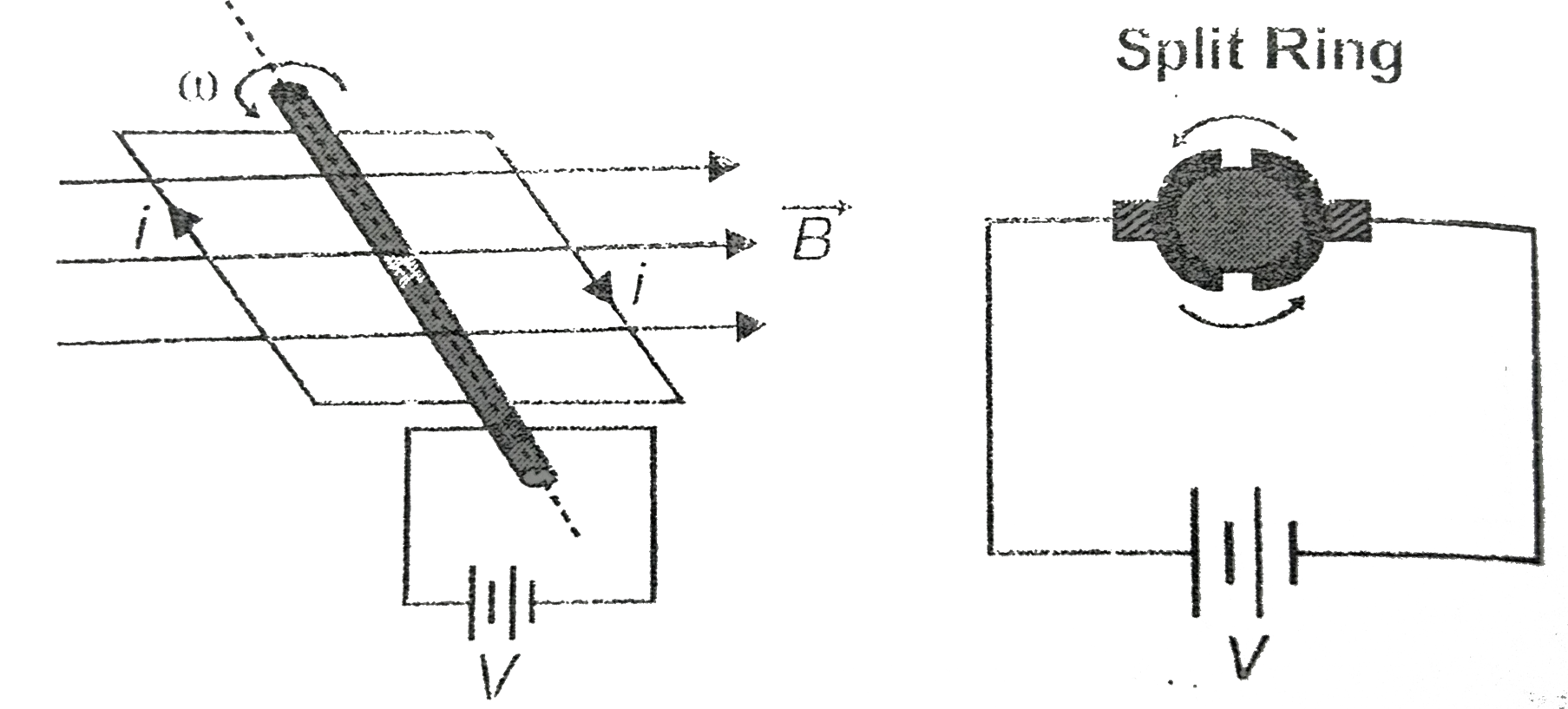
The coil rotates under the action of torque. The current is supplied to the coil by an arrangement of two sliding contacts and a split ring. As the coil rotates, the magnetic flux linked with the coil changes. This leads to production of an induced emf ε in the coil. By Lenz's law, the induced emf opposes the applied voltage and therefore, it is called back emf. If R is the resistance in the coil, the current i flowing through the coil at any instant is i=V−εR. The back emf is developed due to induction and it is directly proportional to speed of rotation and it is directly proportional to speed of rotation of the motor. There is a continuous power loss i2R in the motor, in form of heat.
When a dc motor is running unloaded (full speed) the current through it is 1 A. What will be the current flowing through the motor, when it is loaded to run at half its maximum speed, it applied voltage is 10 V and armature resistance is 5Ω
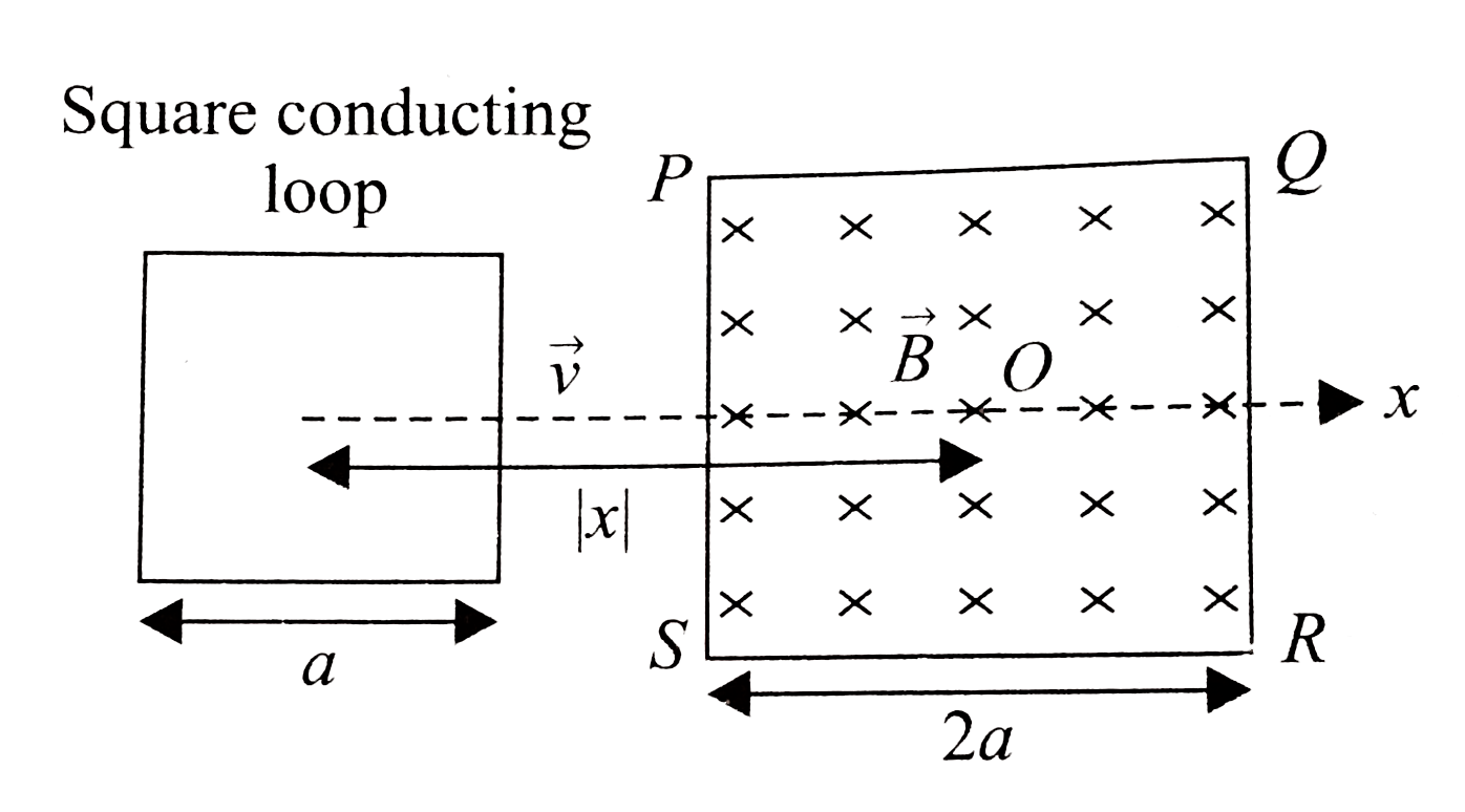
View SolutionPQRS is a square region of side 2a in the plane of paper. A uniform magnetic field B, directed perpendicular to the plane of paper and into its plane is confined within this square region. A square loop of side 'a' and made of a conducting wire of resistance R is moved at a constant velocity →v from left to right in the plane of paper as shown. Obviously, the square loop will enter the magnetic field at some time and then leave it after some time. During the motion of loop, whenever magnetic flux through it changes, emf will be induced resulting in induced current. Let the motion of the square loop be along x-axis and let us measure x coordinate of the centre of square loop from the centre of the square magnetic field region (taken as origin). Thus, x coordinate will be positive if the centre of square loop is to the right of the origin O (centre of magnetic field) and negative if centre is to the left.
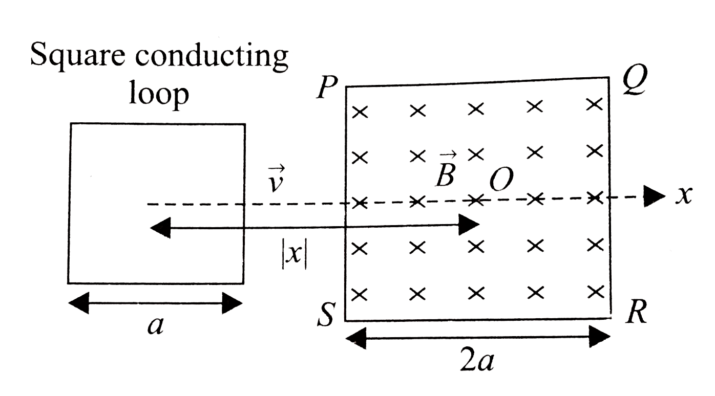
For x=a/4
(i) magnetic flux through the loop,
(ii) induced current in the loop and
(iii) external force required to maintain constant velocity of the loop, will be
View SolutionPQRS is a square region of side 2a in the plane of paper. A uniform magnetic field B, directed perpendicular to the plane of paper and into its plane is confined within this square region. A square loop of side 'a' and made of a conducting wire of resistance R is moved at a constant velocity →v from left to right in the plane of paper as shown. Obviously, the square loop will enter the magnetic field at some time and then leave it after some time. During the motion of loop, whenever magnetic flux through it changes, emf will be induced resulting in induced current. Let the motion of the square loop be along x-axis and let us measure x coordinate of the centre of square loop from the centre of the square magnetic field region (taken as origin). Thus, x coordinate will be positive if the centre of square loop is to the right of the origin O (centre of magnetic field) and negative if centre is to the left.
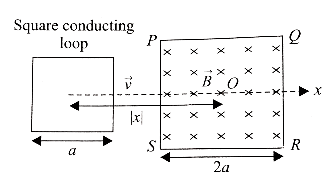
For x=−9a/5, magnitude of induced current and its direction as seen from above will be:
View SolutionPQRS is a square region of side 2a in the plane of paper. A uniform magnetic field B, directed perpendicular to the plane of paper and into its plane is confined within this square region. A square loop of side 'a' and made of a conducting wire of resistance R is moved at a constant velocity →v from left to right in the plane of paper as shown. Obviously, the square loop will enter the magnetic field at some time and then leave it after some time. During the motion of loop, whenever magnetic flux through it changes, emf will be induced resulting in induced current. Let the motion of the square loop be along x-axis and let us measure x coordinate of the centre of square loop from the centre of the square magnetic field region (taken as origin). Thus, x coordinate will be positive if the centre of square loop is to the right of the origin O (centre of magnetic field) and negative if centre is to the left.
External force required to maintain constant velocity of the loop for x=−95a will be
View SolutionExplain briefly, with the help of a labelled diagram, the basic principle of working of an a.c. generator. In an a.c. generator, coil of N turns and area A rotating with a constant angular speed ω in a uniform magnetic field B. Write the expression for the emf produced.
A 100-turn coil of area 0.1m2 rotates at half a revolution per second. It is placed in a magnetic field 0.01 T perpendicular to the axis of rotation of the coil. Calculate the maximum voltage generated in the coil.
View Solution