A weightless rigid rod with a load at the end is hinged at point A to the wall so that it can rotate in all directions (Fig).

The rod is kept in the horizontal position by a vertical inextensible thread of length 1, fixed at its midpoint. The load receives a momentum in the direction perpendicular to the plane of the figure.
Determine the period T of small oscillations of the system.
Step by step video & image solution for A weightless rigid rod with a load at the end is hinged at point A to the wall so that it can rotate in all directions (Fig). The rod is kept in the horizontal position by a vertical inextensible thread of length 1, fixed at its midpoint. The load receives a momentum in the direction perpendicular to the plane of the figure. Determine the period T of small oscillations of the system. by Physics experts to help you in doubts & scoring excellent marks in Class 12 exams.
Updated on:21/07/2023Topper's Solved these Questions
Similar Questions
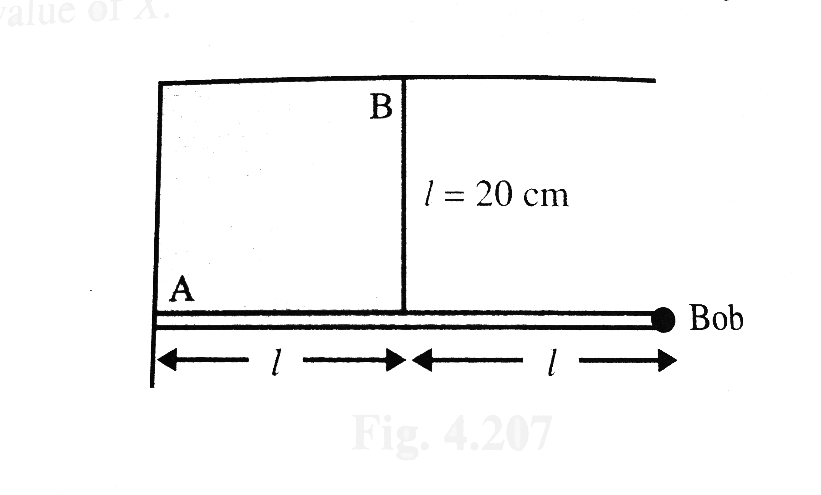
A weightless rigid rod with a small iron bob at the end is hinged at point A to the wall so that it can rotate in all directions. The rod is kept in the horizontal position by a vertical inextensible string of length 20cm, fixed at its midpoint. The bob is displaced slightly perpenducular to the plane of the rod and string. Find period of small oscillations of the system in the form πX10s and fill the value of X.
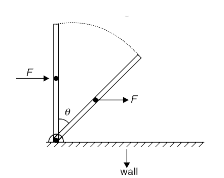
View SolutionA uniform rod of mass M and length L is hinged at its end to a wall so that it can rotate freely in a horizontal plane. When the rod is perpendicular to the wall a constant force F starts acting at the centre of the rod in a horizontal direction perpendicular to the rod. The force remains parallel to its original direction and acts at the centre of the rod as the rod rotates. (Neglect gravity).
(a) With what angular speed will the rod hit the wall ?
(b) At what angle θ (see figure) the hinge force will make a 45∘ angle with the rod ?
View Solution
Knowledge Check
A steel rod of length L, density d and cross-sectional area A, is hinged at one end so that it can rotate freely in a vertical plane. The rod is released from a horizontal position. When it becomes vertical, the stress at its midpoint is
A13dLg8B12dLg8C2dLg5DdLg2A steel rod of length L, density d and cross-sectional area A, is hinged at one end so that it can rotate freely in a vertical plane. The rod is released from a horizontal position. When it becomes vertical, the stress at its midpoint is
A13dLg/8B12dLg /8C2dL g/5DdLg/2A uniform rod AB hinged about a fixed point P is initially vertical. A rod is released from vertical position. When rod is in horizontal position:
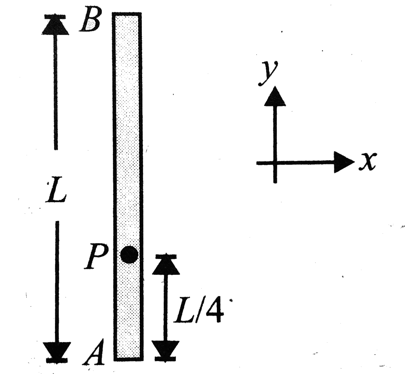
The acceleration of end B of the rod isA−6g7ˆi−12g7ˆjB−5g7ˆi−6g7ˆjC−18g7ˆi−5g7ˆjD−18g7ˆi−9g7ˆj
Four weightless rods of length l each are connected by hinged joints and form a rhomb (Fig). A hinge A is fixed, and a load is suspended to a hinge C. Hinges D and B are connected by a weightless spring of length 1.5l in the undeformed state. In equilibrium, the rods form angles α0=30∘ with the vertical. Determine the period T of small oscillations of the load.

View SolutionA uniform rod AB hinged about a fixed point P is initially vertical. A rod is released from vertical position. When rod is in horizontal position:
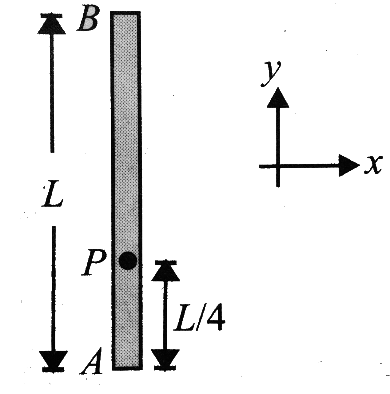
The reaction at hinge P is
View SolutionA uniform rod AB hinged about a fixed point P is initially vertical. A rod is released from vertical position. When rod is in horizontal position:
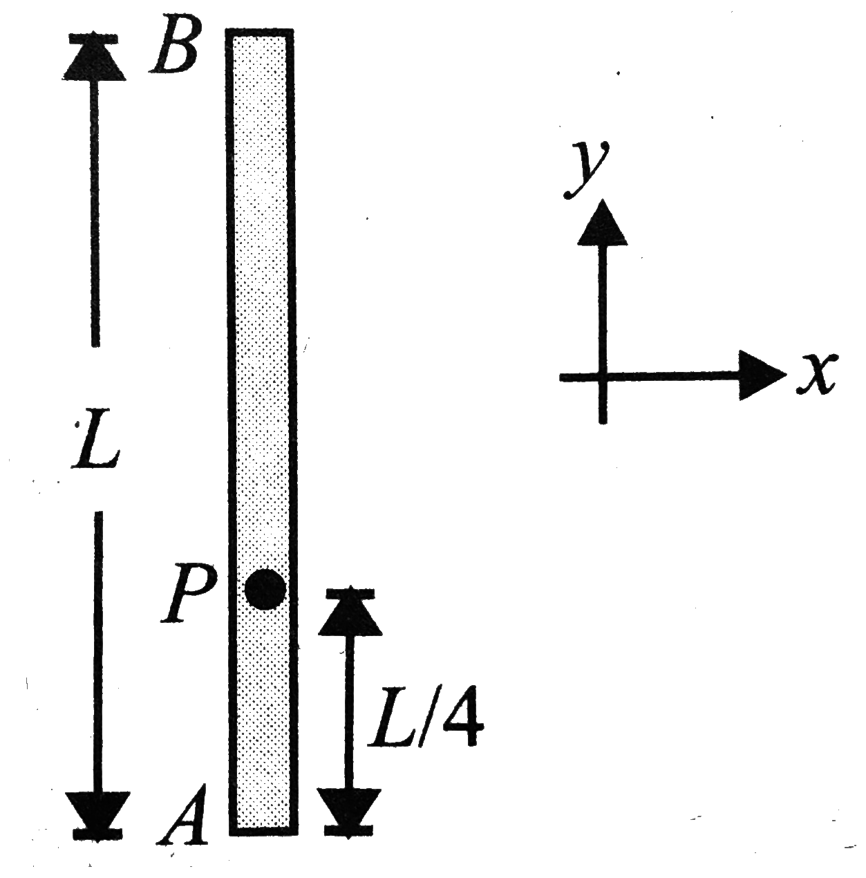
The acceleration of the centre of mass of the rod is
View Solution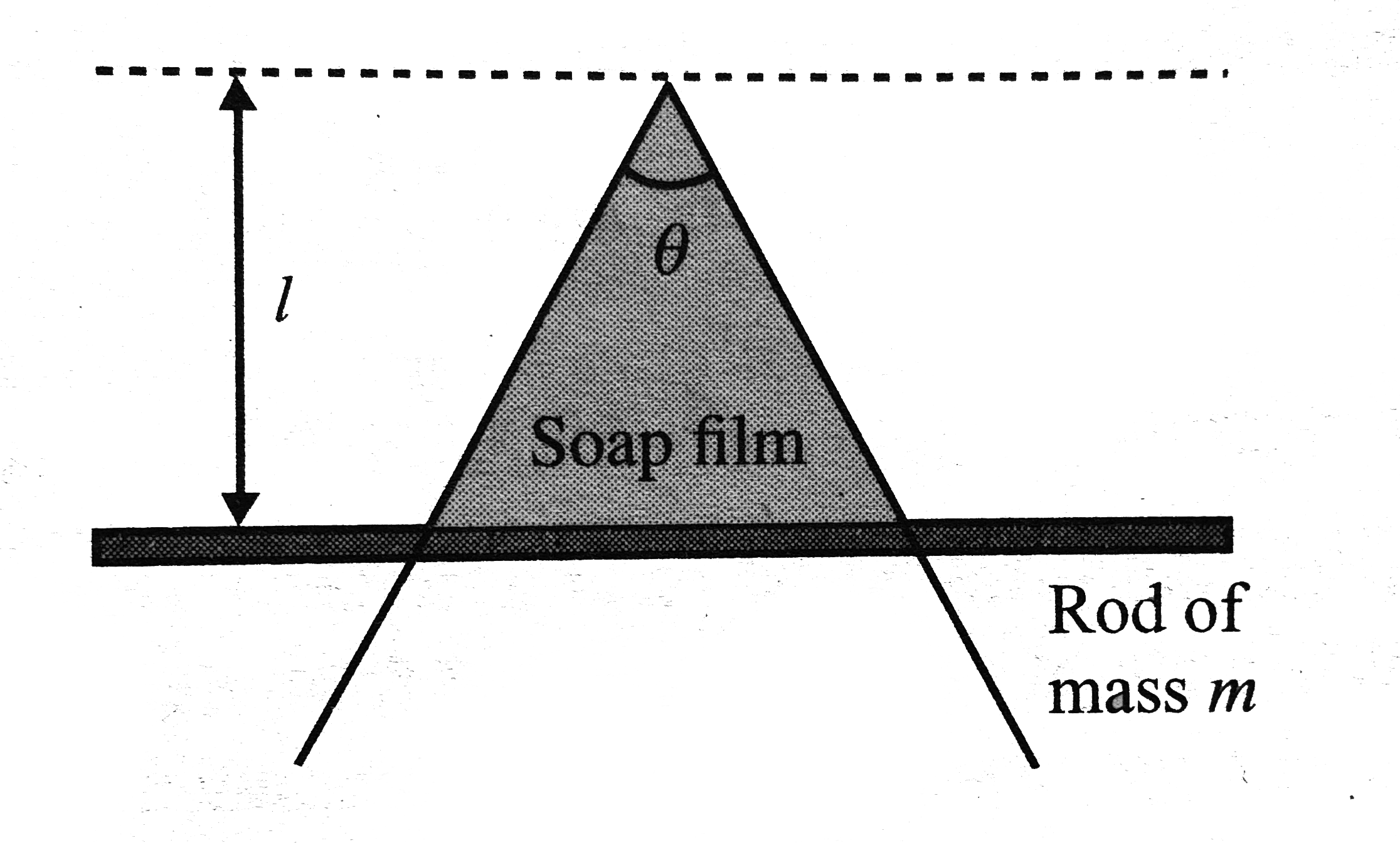
A wire is bent an an angle θ. A rod of mass m can slide along the bended wire without friction as shown in Fig. A soap film is maintained in the frame kept in a vertical position and the rod is in equilibrium as shown in the figure. If rod is displaced slightly in vertical direction, then the time period of small oscillation of the rod is
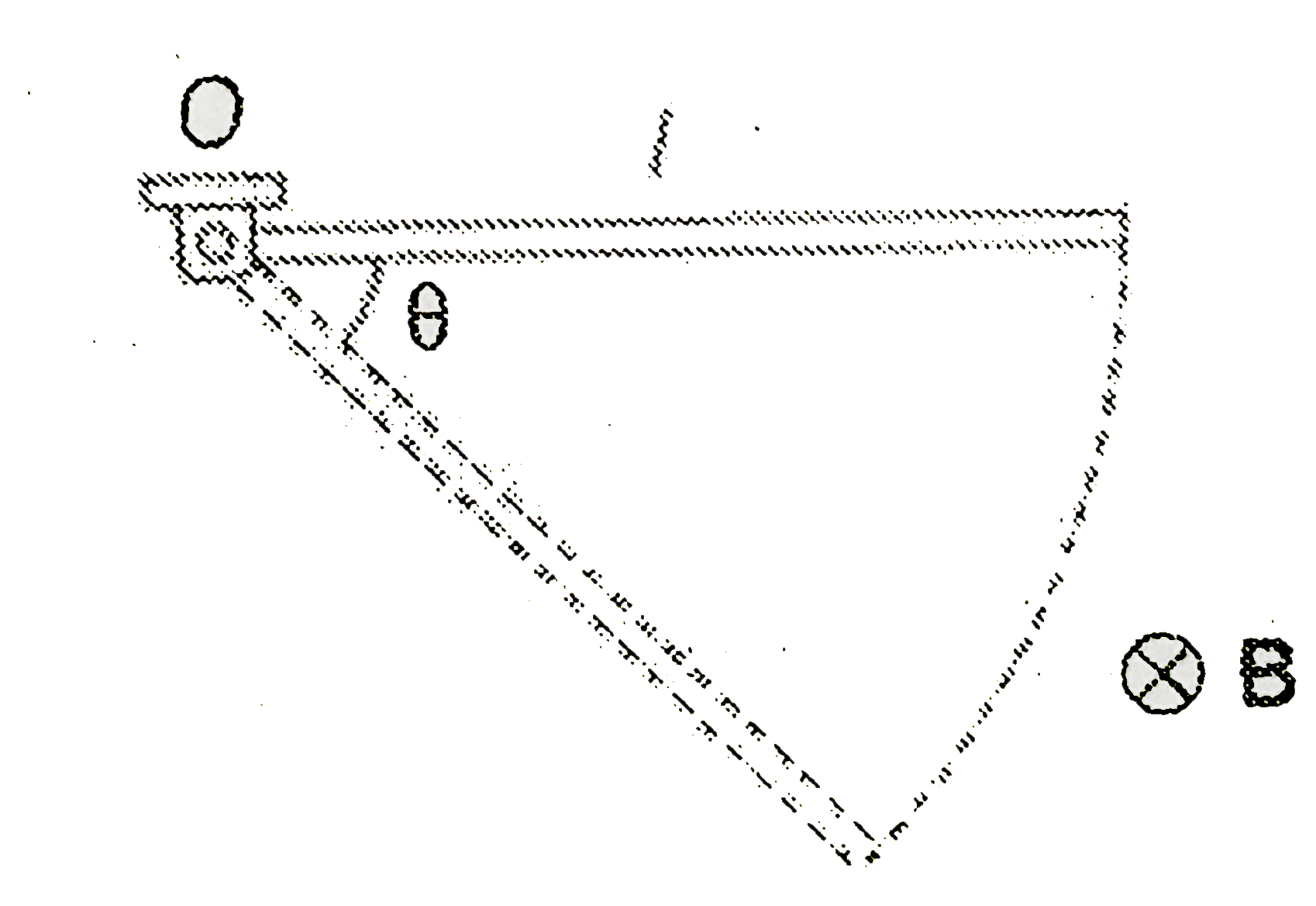
View SolutionA conducting rod of length l is hinged at point O. It is a free to rotate in a verical plane. There exists a uniform magnetic field B in horizontal direction. The rod is released from the position shown. The potential difference between the two ends of the rod is proportional to
View Solution
