In the figure shown V1,V2,V3 are AC voltmeters and A is AC ammeter. The readings of V1,V2,V3 and 10V,20V,20V,2A respectively. If the inductor is short circuited, then
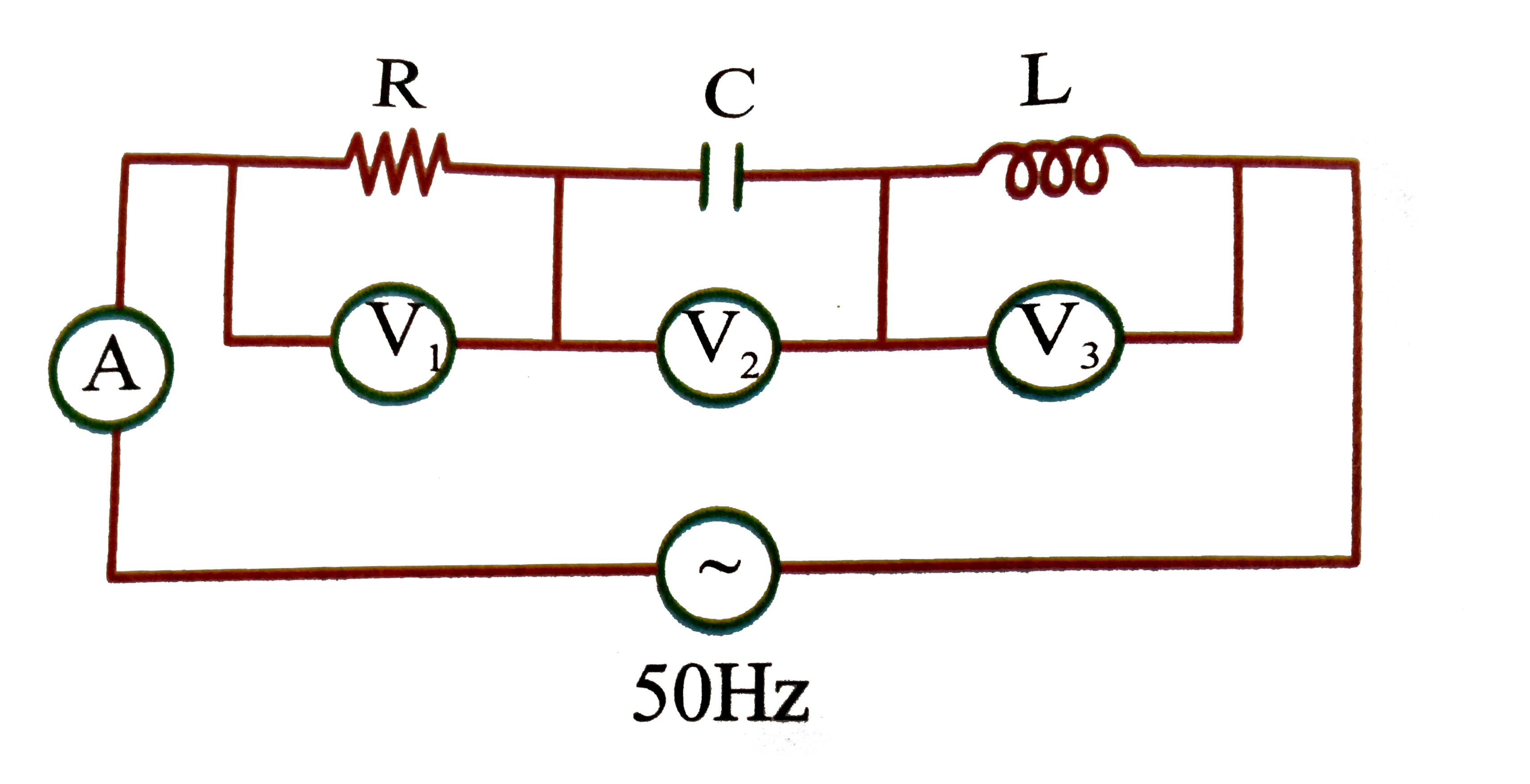
the reading of V1 is 2√5V
the reading of V2 is 4√5V
the reading of V2 is 2√5V
the value of A is 2√5A
The correct Answer is:A,B,D
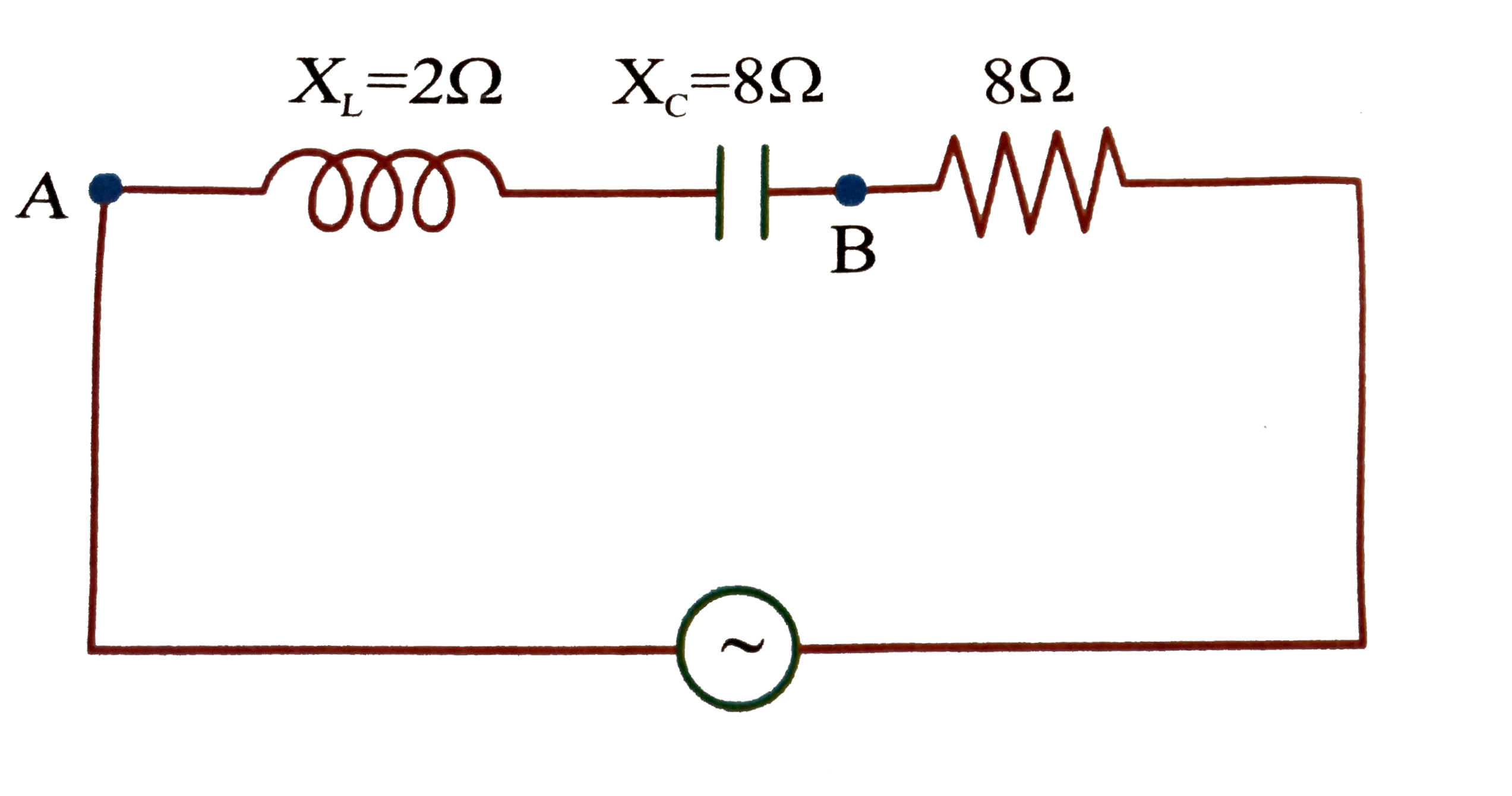
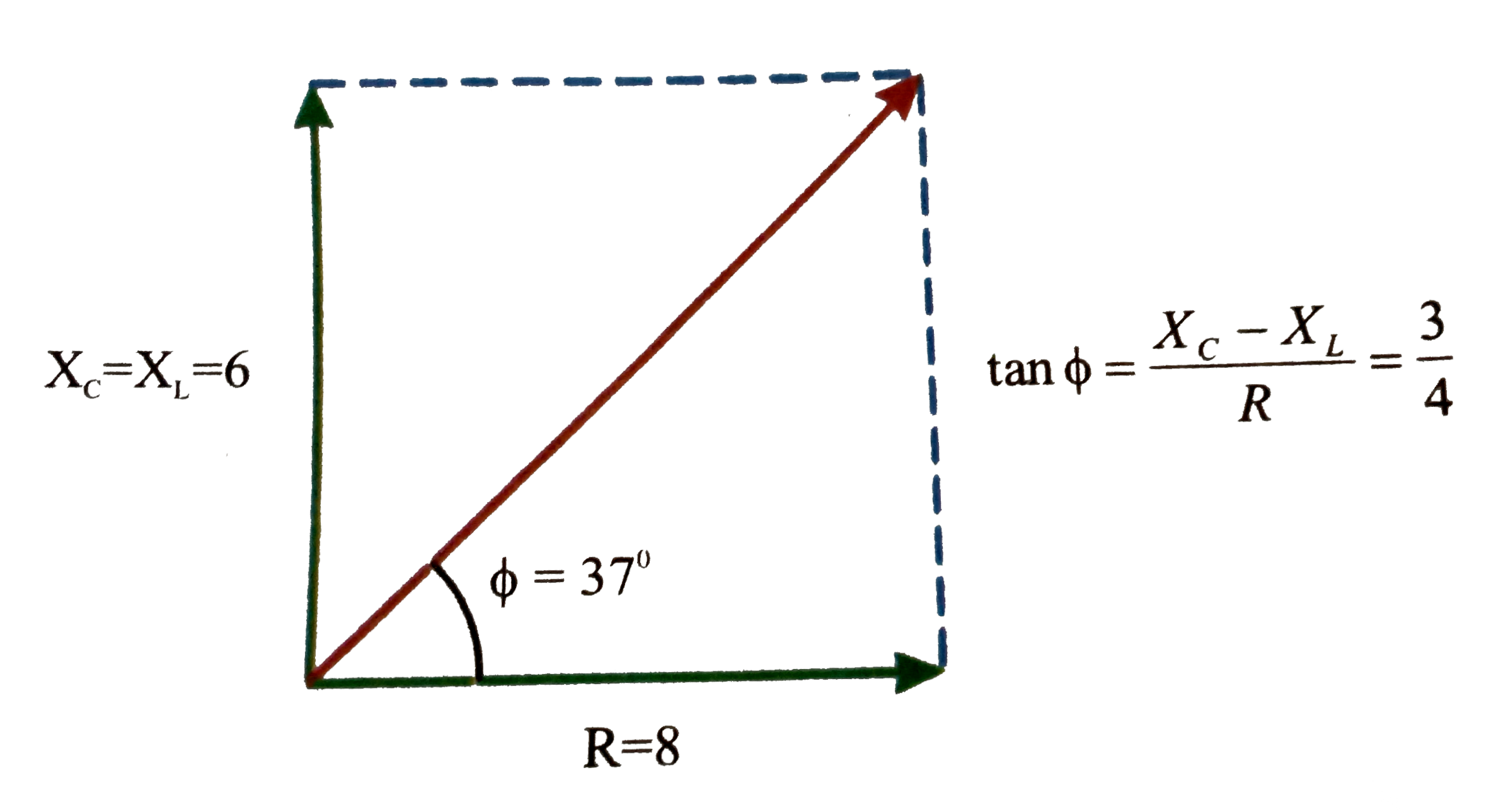
(a) Impedance of circuit =√R2+(XC+XL)2
Z=√82+(8−2)2=10Ω
(b) The current leads in phase by (∴'Xc>XL)ϕ=37∘
∴i=(10cos(100πt+37∘)Z=cos(100πt+37∘)
The instantaneous potential difference across AB is
=Im=(XC−XL)cos(100πt+37∘−90∘)
=6cos(100πt−53∘)
The instantaneous petential difference across AB is half of source voltage.
=6cos(100πt−53∘)=5cos100πt
Solving, Tan(100πt)=1724
∴t=1100πTan−1(1724)
Topper's Solved these Questions
- ALTERNATING CURRENTBook:NARAYNAChapter:ALTERNATING CURRENTExercise:LEVEL - I (H.W)
Explore 23 Videos
- ALTERNATING CURRENTBook:NARAYNAChapter:ALTERNATING CURRENTExercise:LEVEL - II(H.W)
Explore 13 Videos
- ALTERNATING CURRENTBook:NARAYNAChapter:ALTERNATING CURRENTExercise:LEVEL - V
Explore 83 Videos
- ATOMIC PHYSICSBook:NARAYNAChapter:ATOMIC PHYSICSExercise:LEVEL-II (H.W)
Explore 14 Videos
Similar Questions
If reading of voltmeter V1 is 40 V, what is the reading of voltmeter V2?
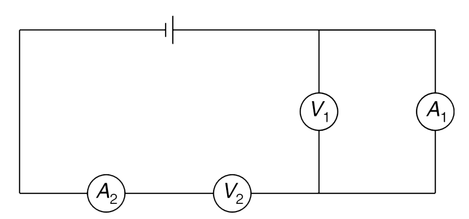
View SolutionIn the circuit shown in figure the voltmeters V1&V2 are identical. If readings of ammeter A2, Voltmeter V2andV1 are 400μA,100Vand2V respectively, find the resistance of ammeter A1. Is the value realistic ?
View Solution
Knowledge Check
If the readings V1 and V3 are 10. volt each, then reading of V2 is:
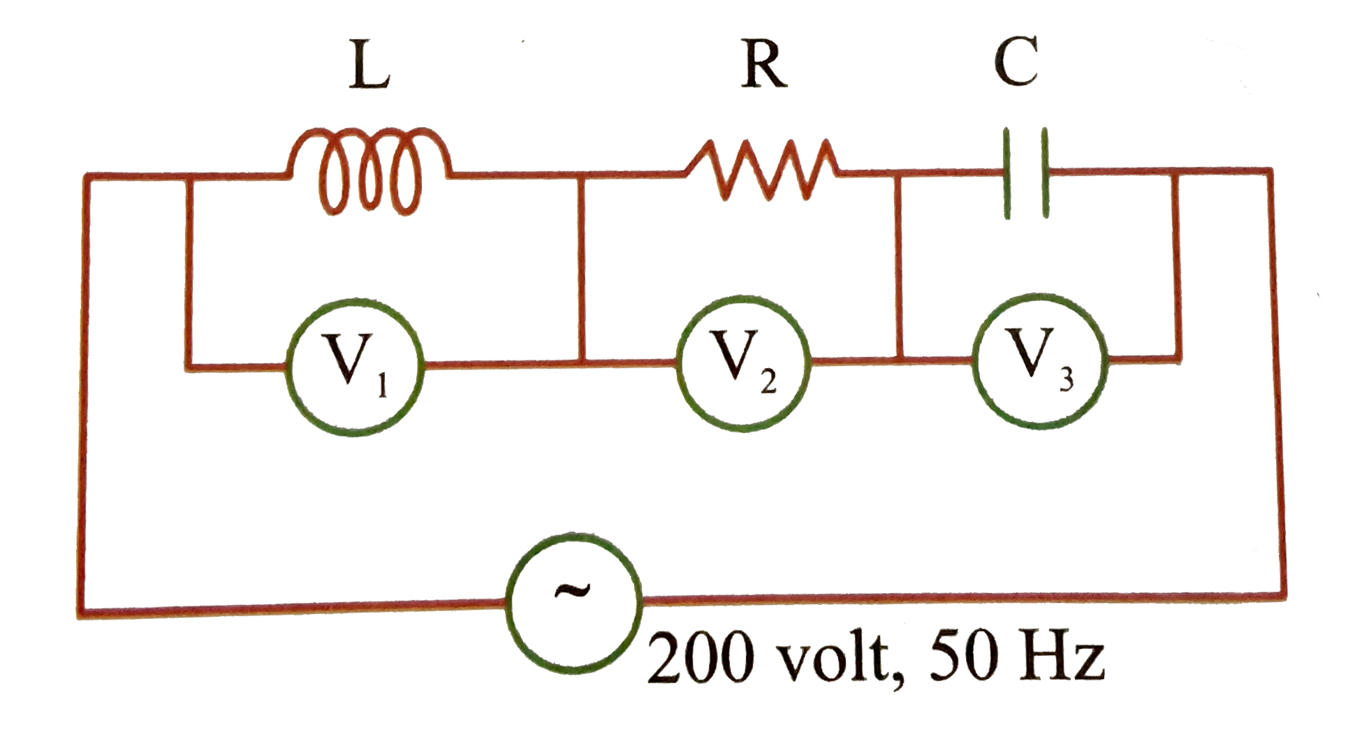 A0 voltB100 voltC200 voltDcannot be determined by given information
A voltmeter reads V volts in an A.C. circuit then V is
Apeak value of the voltageBpeak value of the currentCr.m.s. value of the currentDr.m.s. value of the voltage
In the circuit shown, the readings of voltmeters V1,V2andV3 are given by
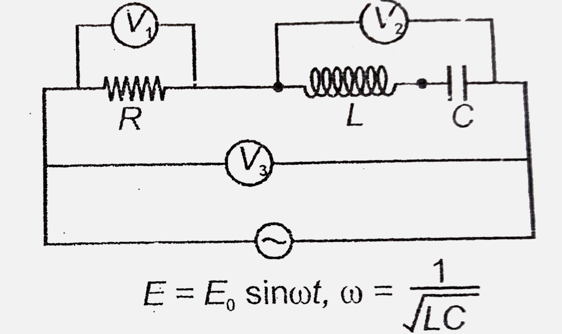
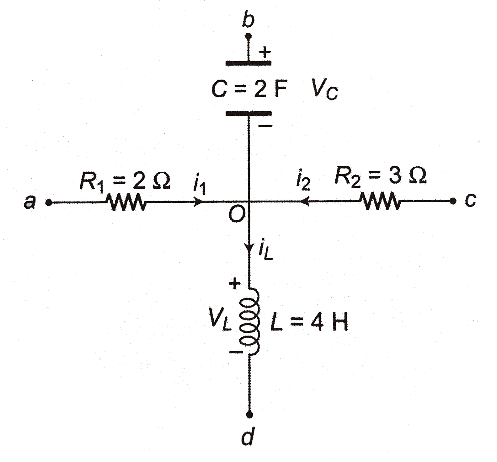
View SolutionIn the figure shown, i1=10e2tA , i2=4A and Vc=3e−2tV Determine
(a) iL and VL
(b) Vac , Vab and Vcd
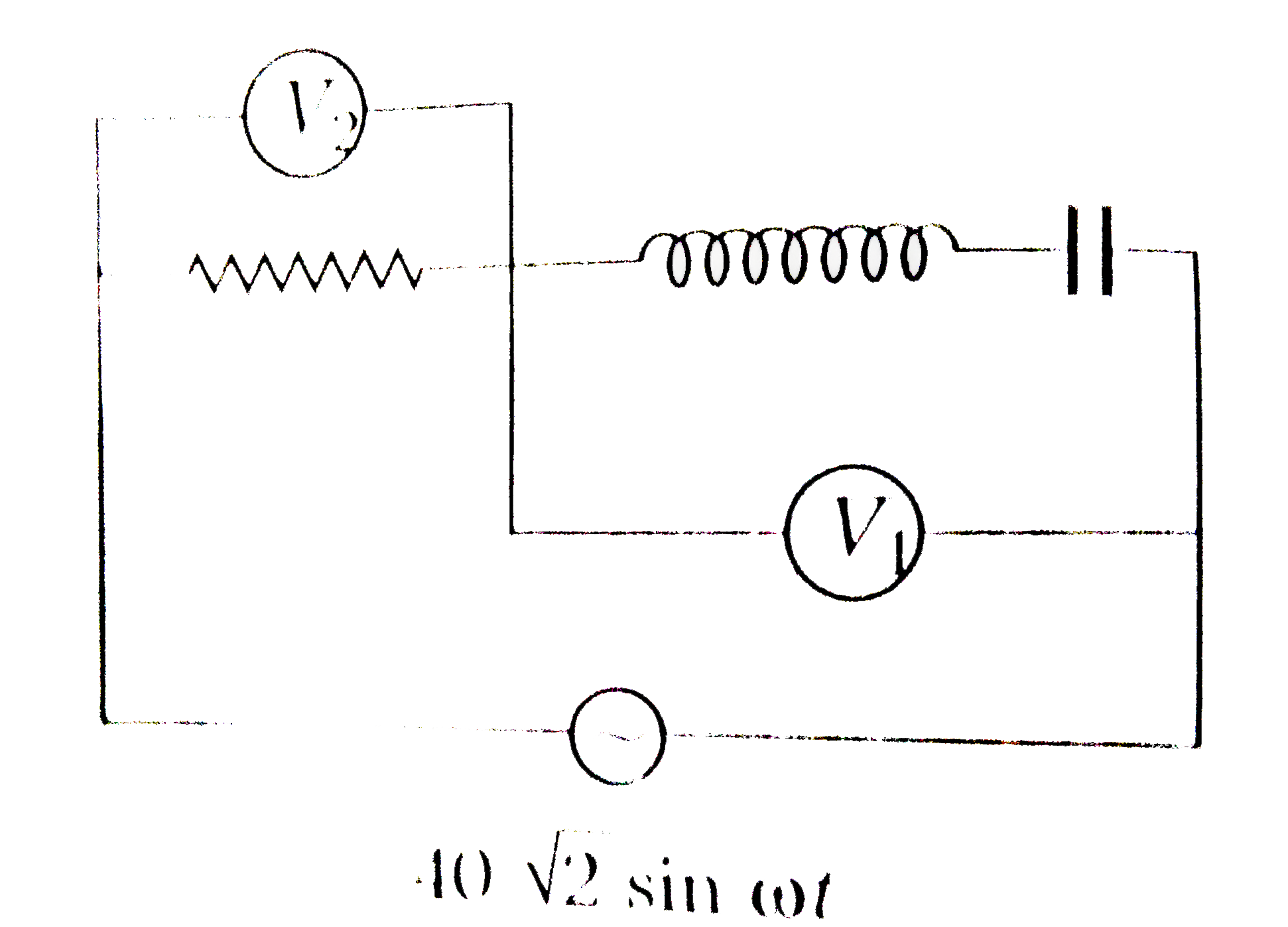
View SolutionIf the reading of volmeter V1 is 30 V, what is the reading of voltmeter V2 ?
View SolutionIn the series LCR circuit as shown in the figure, the voltmeter V and ammeter A reading are
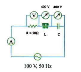
View SolutionIn the series LCR circuit as shown in the figure, the voltmeter V and ammeter A reading are

View SolutionThree capacitors C1,C2 and C3 are connected as shown in, The potentials of P,Q, and R are V1,V2, and V3, respectively. Find the potential V0 at the functionO.
 .
.
View Solution
