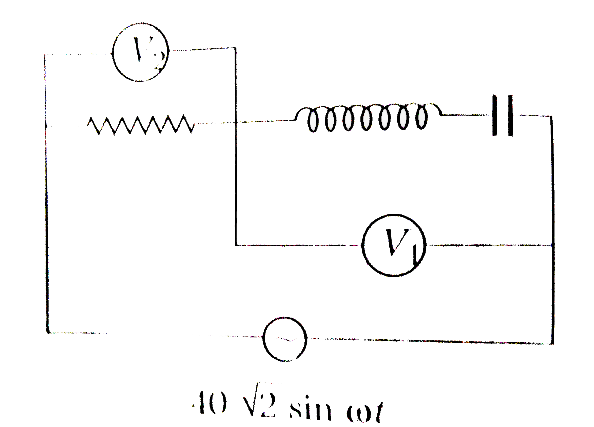
If reading of voltmeter V1 is 40 V, what is the reading of voltmeter V2?
To solve the problem step by step, we will analyze the given information and apply the relevant formulas from the LCR circuit theory.
Step 1: Understand the circuit
We have an LCR circuit with two voltmeters, V1 and V2. We know that V1 is the voltage across a certain component (likely the resistor) and is given as 40 V.
Step 2: Identify the formula for Vrms
In an LCR circuit, the root mean square (RMS) voltage can be expressed as:
V2rms=V2R+V2L/C
where VR is the voltage across the resistor and VL/C is the voltage across the inductor and capacitor combined.
Step 3: Calculate Vrms
From the problem, we have:
Vrms=50√2sin(ωt)
To find the RMS value, we use:
Vrms=V0√2=50√2√2=50V
Step 4: Substitute known values into the formula
Now we substitute Vrms and V1 into the formula:
502=V2R+402
This simplifies to:
2500=V2R+1600
Step 5: Solve for VR
Rearranging the equation gives:
V2R=2500−1600=900
Taking the square root:
VR=√900=30V
Step 6: Conclusion
The reading of voltmeter V2 (which represents the voltage across the resistor) is:
V2=30V
Summary of Steps
1. Understand the circuit and the given voltages.
2. Identify the formula for RMS voltage in an LCR circuit.
3. Calculate the RMS voltage using the peak voltage.
4. Substitute the known values into the RMS voltage equation.
5. Solve for the unknown voltage across the resistor.
6. Conclude with the value of V2.
We have an LCR circuit with two voltmeters, V1 and V2. We know that V1 is the voltage across a certain component (likely the resistor) and is given as 40 V.
In an LCR circuit, the root mean square (RMS) voltage can be expressed as:
V2rms=V2R+V2L/C
where VR is the voltage across the resistor and VL/C is the voltage across the inductor and capacitor combined.
From the problem, we have:
Vrms=50√2sin(ωt)
To find the RMS value, we use:
Vrms=V0√2=50√2√2=50V
Now we substitute Vrms and V1 into the formula:
502=V2R+402
This simplifies to:
2500=V2R+1600
Rearranging the equation gives:
V2R=2500−1600=900
Taking the square root:
VR=√900=30V
The reading of voltmeter V2 (which represents the voltage across the resistor) is:
V2=30V
1. Understand the circuit and the given voltages.
2. Identify the formula for RMS voltage in an LCR circuit.
3. Calculate the RMS voltage using the peak voltage.
4. Substitute the known values into the RMS voltage equation.
5. Solve for the unknown voltage across the resistor.
6. Conclude with the value of V2.
Topper's Solved these Questions
- ALTERNATING CURRENT Book:AAKASH INSTITUTEChapter:ALTERNATING CURRENT Exercise:Try Yourself
Explore 15 Videos
- ALTERNATING CURRENT Book:AAKASH INSTITUTEChapter:ALTERNATING CURRENT Exercise:Assignment (Section - A) ( Objective Type Questions ( One option is correct))
Explore 34 Videos
- ATOMSBook:AAKASH INSTITUTEChapter:ATOMSExercise:ASSIGNMENT SECTION J (Aakash Challengers )
Explore 4 Videos
Similar Questions
If the reading of volmeter V1 is 30 V, what is the reading of voltmeter V2 ?
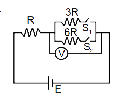
View SolutionIn the circuit shown in figure reading of voltmeter is V1 when only S1 is closed , reading of voltmeter is V2 when only S2 is closed . The reading of voltmeter is V3 when both S1 and S2 are closed then
View Solution
Knowledge Check
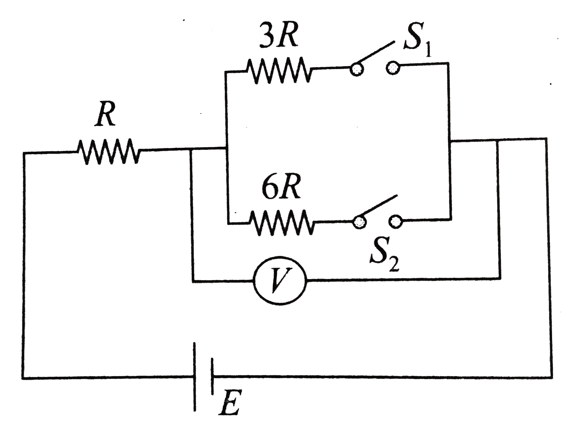
In the circuit shown in figure, reading of voltmeter is V1 when only S1 is closed, reading of voltmeter is V2 when only S2 is closed, and reading of voltmeter is V3 when both S1andS2 are closed. Then .
 AV3>V2>V1BV2>V1>V3CV3>V1>V2DV1>V2>V3
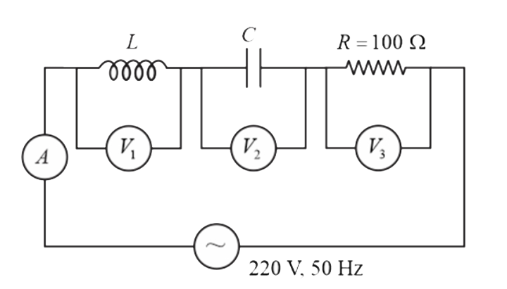
In the given circuit the reading of voltmeters V1andV2 are 300 volt each . The reading of the voltmeter V3 and ammeter A are respectively
 A150 V and 2.2 AB220 V and 2.2 AC220 V and 2.0 AD100 V and 2.0 A
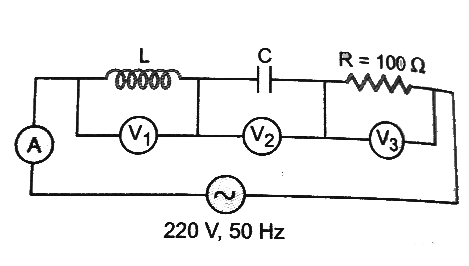
In the given circuit, Fig., the reading of voltmeter V1 and V2 300 votls each. The reading of the voltemeter V3 and ammeter A are respectively
 A150V,2.2AB220V,2.2AC220V,2.0AD100V,2.0A
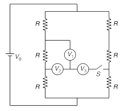
In the circuit shown in figure all resistances are identical (each equal to R) and the cell has an emf of V0. The three voltmeters V1,V2andV3 are identical and are nearly ideal.
(a) find the reading of the voltmeter V1 when switch ‘S’ is open.
(b) find the reading of the voltmeter V1 after the switch is closed
View SolutionAn ammeter and a voltmeter are connected in series to a battery of emf 6V. When a certain resistance is connected in parallel with the voltmeter, the reading of the latter decreases n = 2 times, whereas the reading of the ammeter increases the same number of times. What is the ratio of the voltmeter resistance to the ammeter resistance? Find the voltmeter reading after the connection.
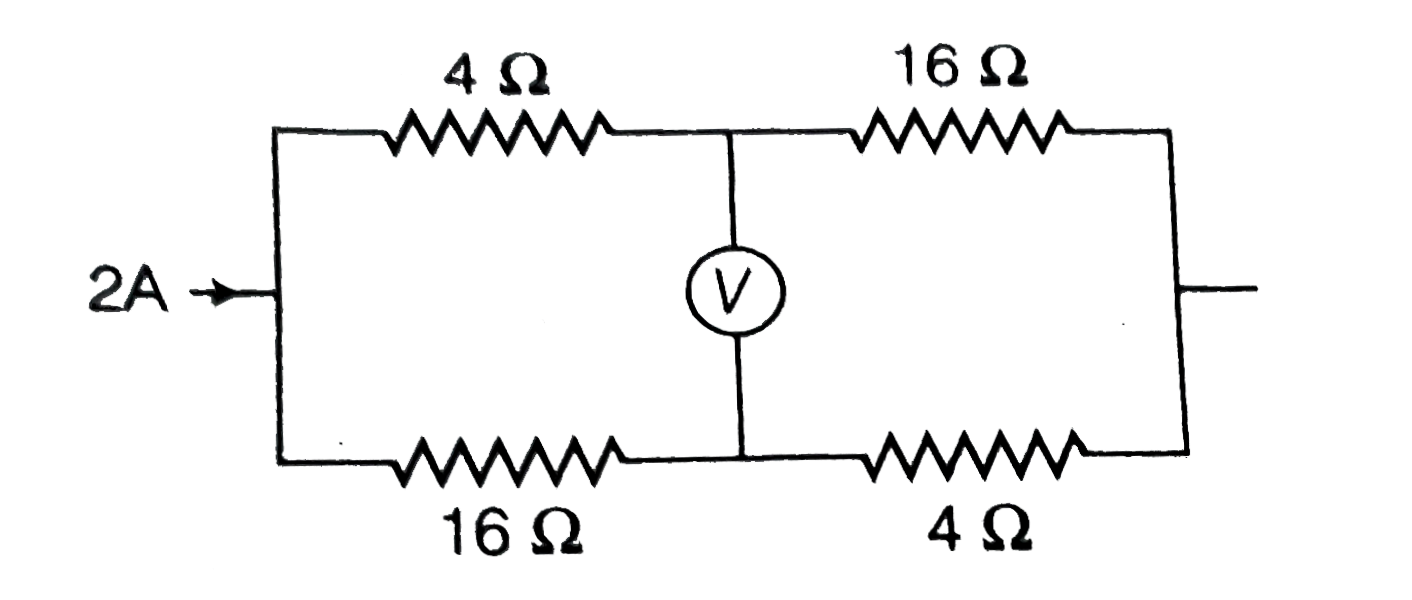
View SolutionIn the following circuit reading of voltmeter V is
View SolutionTwo identical voltmeters and two identical ammeter are connected to a battery of negligible resistance shown in the figure. The readings of devices are follows
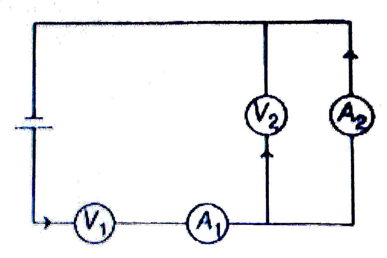
Reading of Ammeter A1=200μA
Reading of voltmeter V2=2 volt
Reading of voltmeter V1=100 volt
Choose the correct option(s)
View SolutionIf potential gradient on wire PQ is 0.01V/m then the reading of voltmeter is :
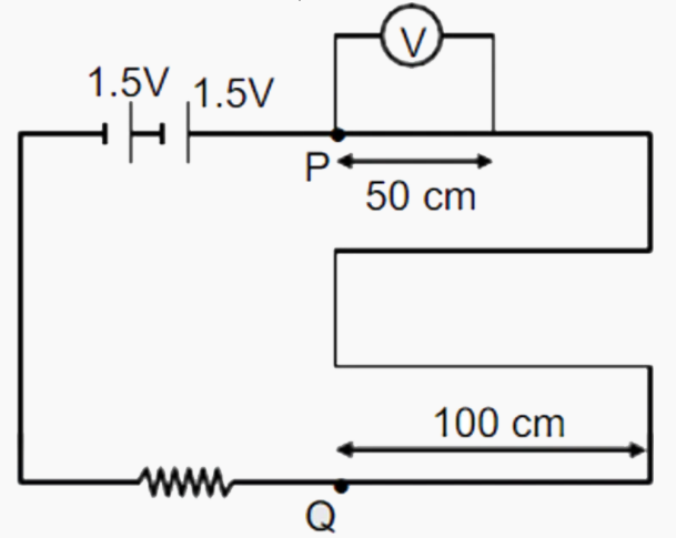
View Solution

