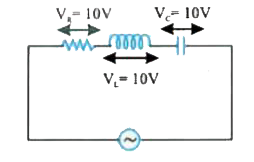
One application of L−R−C series circuit is in high pass or low pass filter, which out either the low or high frequency components of a signal. A has pass filter is shown in figure where the output voltage is taken across the L−R where L−R combination represents and inductive coil that also has resistance due to the large length of the wire in the coil.
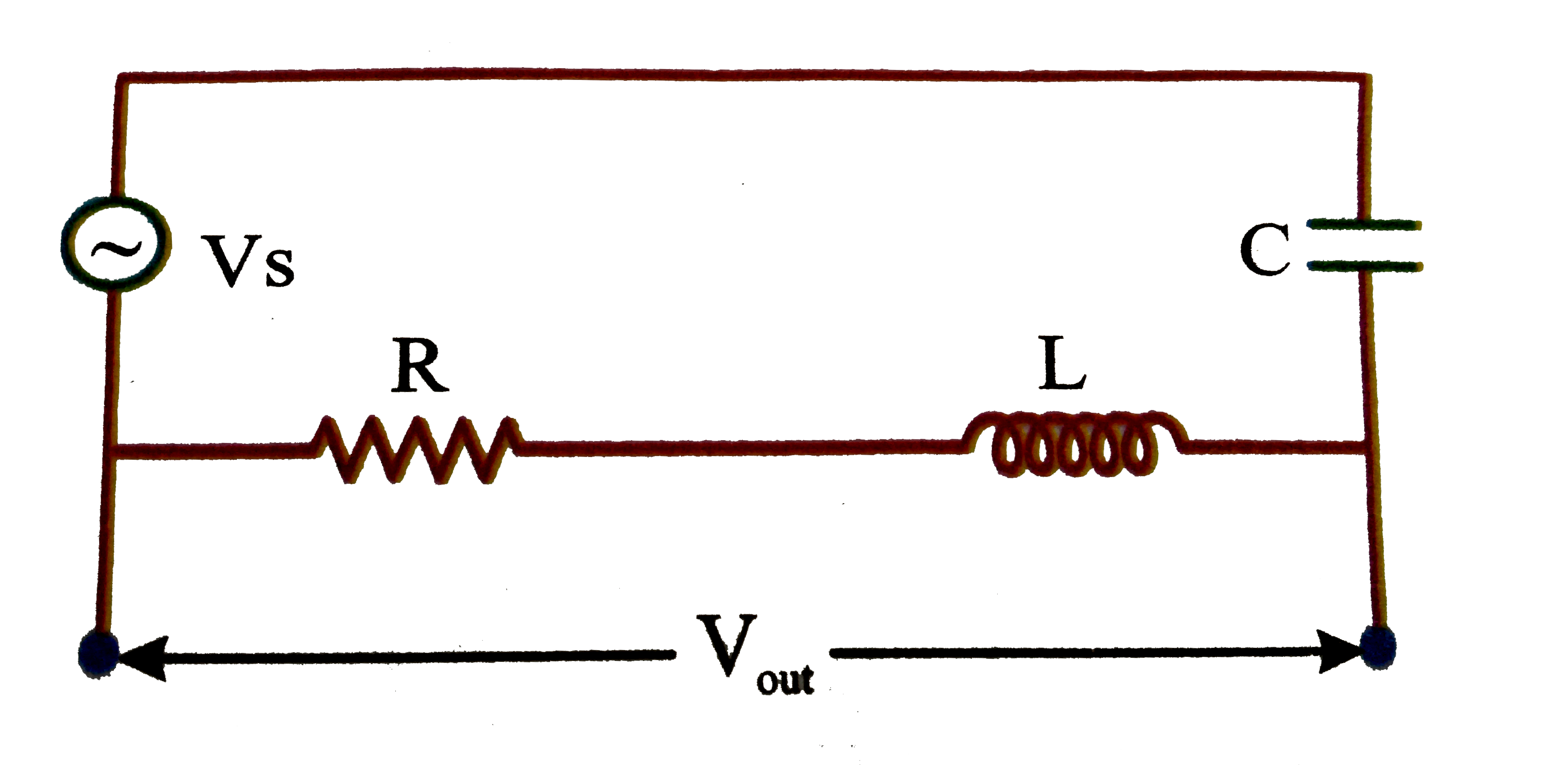
Which statement is correct in the limit of large frequency is reached? (for Vout/Vs)
1
ωRC
ωRL
ωRL
The correct Answer is:A
As ω→∞, VoutVs=1
Topper's Solved these Questions
- ALTERNATING CURRENTBOOK - NARAYNACHAPTER - ALTERNATING CURRENTEXERCISE - LEVEL - I (H.W)
23 Videos
- ALTERNATING CURRENTBOOK - NARAYNACHAPTER - ALTERNATING CURRENTEXERCISE - LEVEL - II(H.W)
13 Videos
- ALTERNATING CURRENTBOOK - NARAYNACHAPTER - ALTERNATING CURRENTEXERCISE - LEVEL - V
83 Videos
- ATOMIC PHYSICSBOOK - NARAYNACHAPTER - ATOMIC PHYSICSEXERCISE - LEVEL-II (H.W)
14 Videos
Similar Questions
Knowledge Check
One application of L−R−C series circuit is in high pass or low pass filter, which out either the low or high frequency components of a signal. A has pass filter is shown in figure where the output voltage is taken across the L−R where L−R combination represents and inductive coil that also has resistance due to the large length of the wire in the coil.
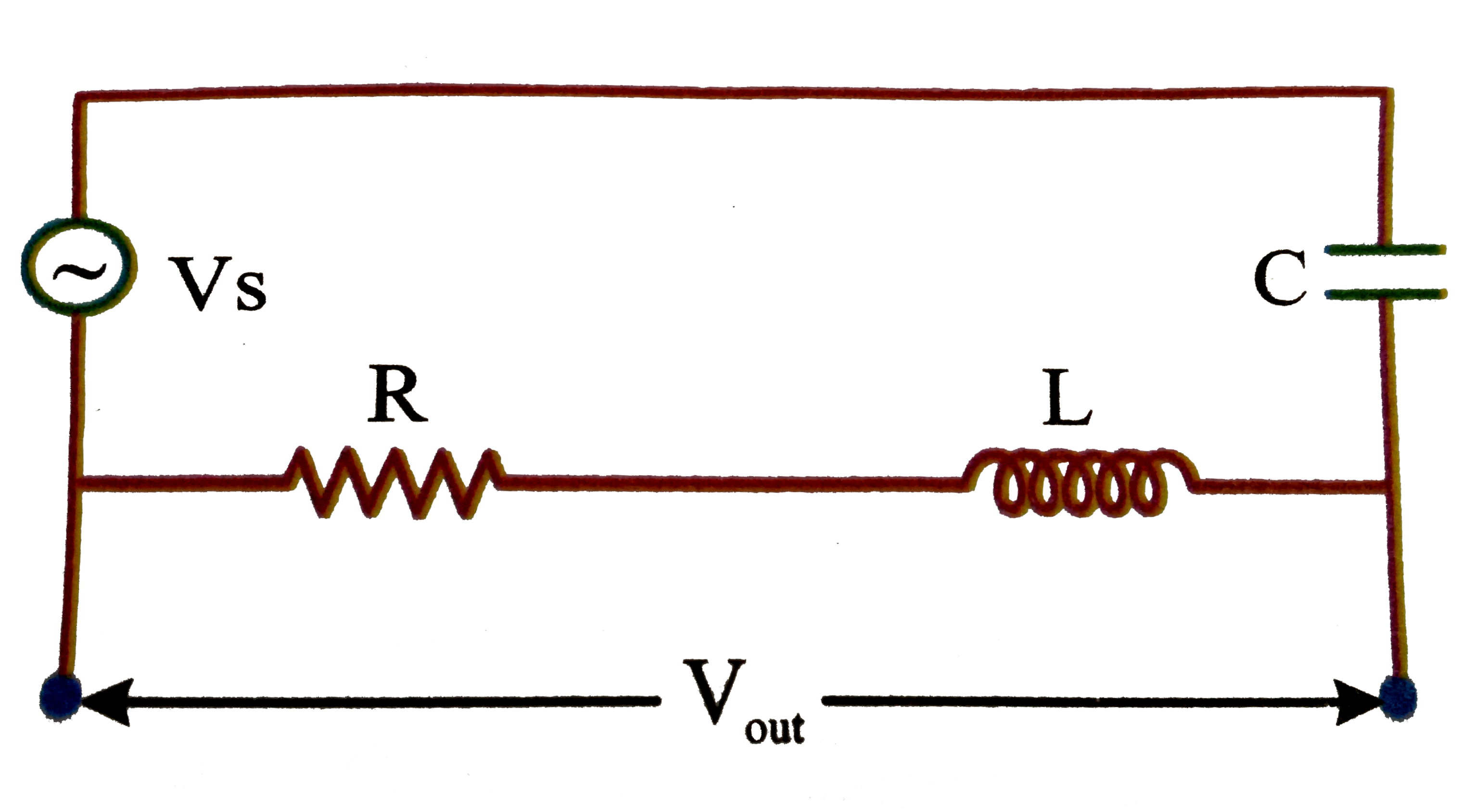
which of the following statementds is correct when ω is samll in the case of Vout/VsAωRCBωRLCωRLDωRCOne application of L−R−C series circuit is in high pass or low pass filter, which out either the low or high frequency components of a signal. A has pass filter is shown in figure where the output voltage is taken across the L−R where L−R combination represents and inductive coil that also has resistance due to the large length of the wire in the coil.
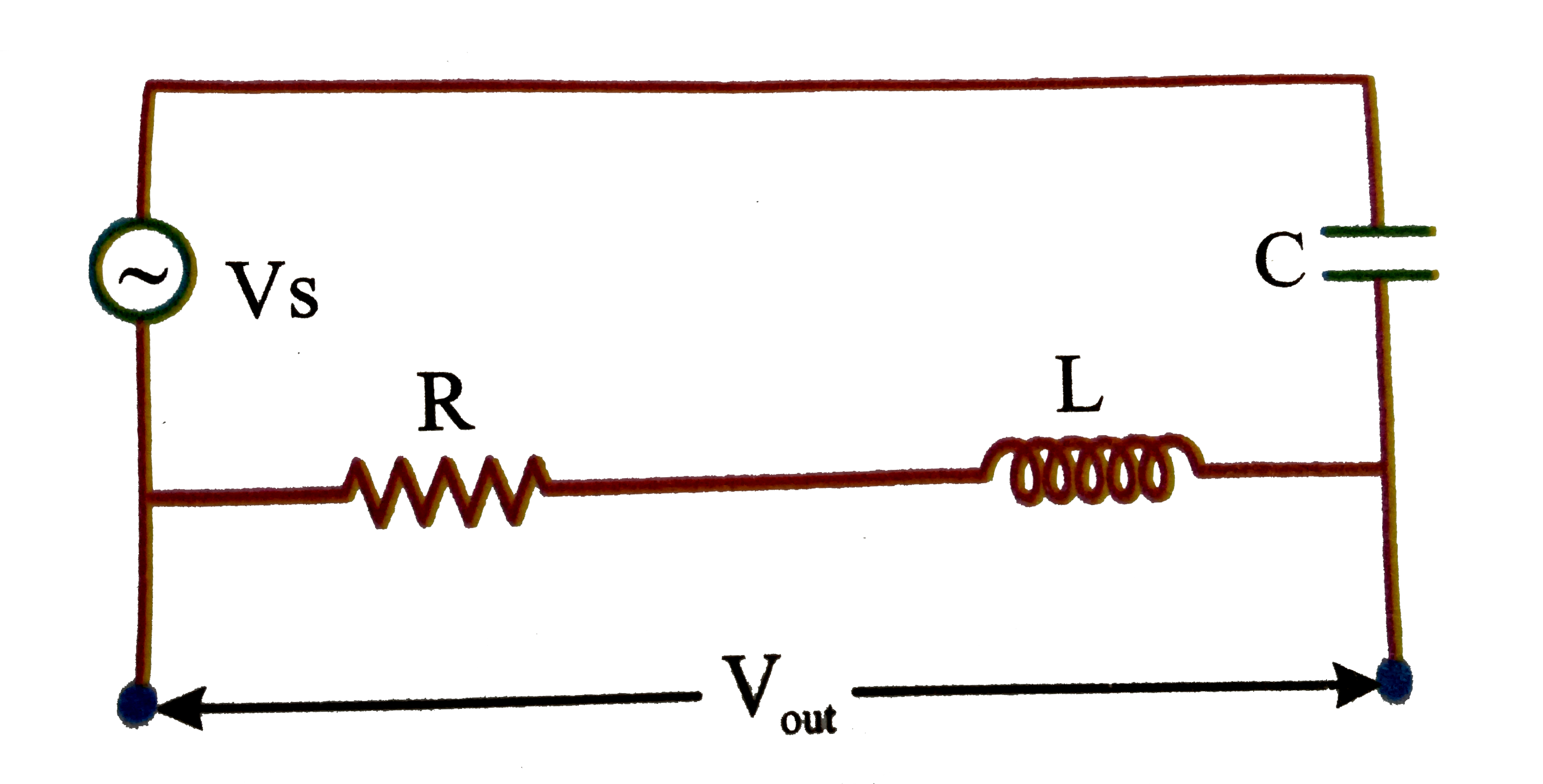
Find the ratio Vout/Vs as a function of the angular frequency ω of the sourceA ⎷R2+ωL2R2+(ωL−1ωC)2B ⎷R2+ω2L2R2+(ωL−1ωC)2C ⎷R2+ω2LR2+(ωC−1ωL)2D1A sinusoidal voltage Vsin(at) is applied across a series combination of resistance R and inductor L. The amplitude of the current in the circuit is
AV0√R2+ω2L2BV0√R2−ω2L2CV0√R2+ω2L2sinωtDVsqrtR
The circuit given in fig. has a resistanceless choke coil L and a resistance R. The voltage across R and L are also given in the figure. The virtual value of the applied voltage is
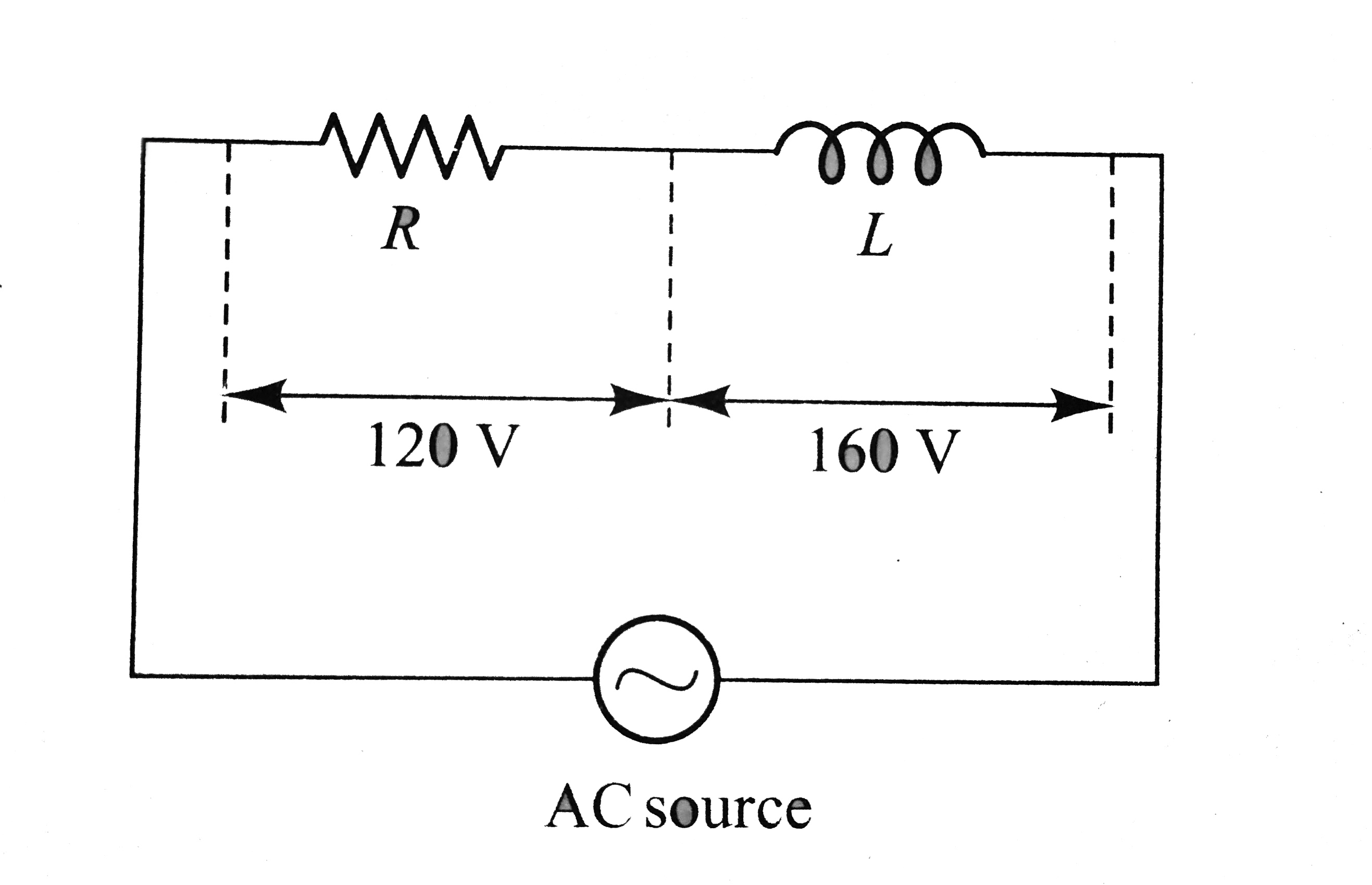
View SolutionAn L−C−R series circuit has a maximum current of 5A. If L=0.5H and C=8μF, then the angular frequency of AC voltage is
View SolutionA coil resistance R and inductance L is connected to a battery of emf E volt. The final current in the coil is
View SolutionWhen a battery is connected across a series combination of self-inductance L and resistance R, the variation in the current I with time t is the best represented by
View SolutionL,C and R represent the physical quantities inductance, capacitance and resistance respectively. Which of the following combinations have dimensions of frequency?
View Solution

