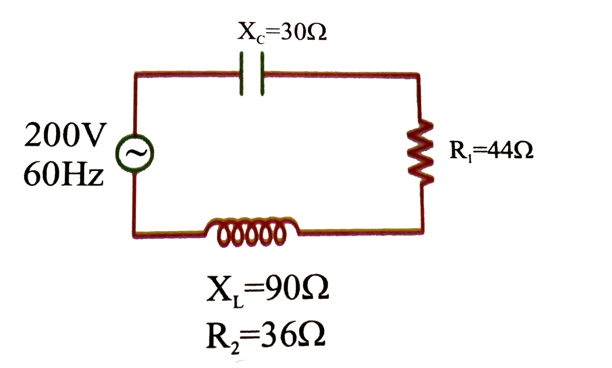
A series circuit connected across a 200V,60Hz line consists of a capacitive reactance 30Ω non inductive resistor of 44Ω and a coil of inductive reactance 90Ω and resistance 36Ω as shown in the diagram

The potentail difference across the coil is
100v
194V
97V
zero
The correct Answer is:B
Step by step video, text & image solution for A series circuit connected across a 200 V, 60 Hz line consists of a capacitive reactance 30 Omega non inductive resistor of 44 Omega and a coil of inductive reactance 90 Omega and resistance 36 Omega as shown in the diagram The potentail difference across the coil is by Physics experts to help you in doubts & scoring excellent marks in Class 12 exams.
Updated on:21/07/2023Topper's Solved these Questions
- ALTERNATING CURRENTBOOK - NARAYNACHAPTER - ALTERNATING CURRENTEXERCISE - LEVEL - I (H.W)
23 Videos
- ALTERNATING CURRENTBOOK - NARAYNACHAPTER - ALTERNATING CURRENTEXERCISE - LEVEL - II(H.W)
13 Videos
- ALTERNATING CURRENTBOOK - NARAYNACHAPTER - ALTERNATING CURRENTEXERCISE - LEVEL - V
83 Videos
- ATOMIC PHYSICSBOOK - NARAYNACHAPTER - ATOMIC PHYSICSEXERCISE - LEVEL-II (H.W)
14 Videos
Similar Questions
As given in the figure, n series circuit coanected across a 200V60HZ line coasists of a capacitor of capacitive reactance 30ohm, sa non-inductive resistar of 44ohm, and a coil of inductive reactance 90ohm and resistance 36ohm. The power dissipated (in watt) in the coil is
'(##CEN_KSR_PHY_JEE_C24_E01_021_Q11##)'
View SolutionAn a.c. circuit an inductive reactance of 80Ωand a pure resistace of 60Ω. What is the impendance of the circuit?
View Solution
Knowledge Check
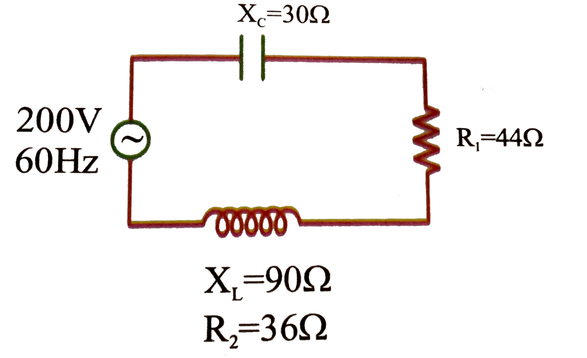
A series circuit connected across a 200V,60Hz line consists of a capacitive reactance 30Ω non inductive resistor of 44Ω and a coil of inductive reactance 90Ω and resistance 36Ω as shown in the diagram

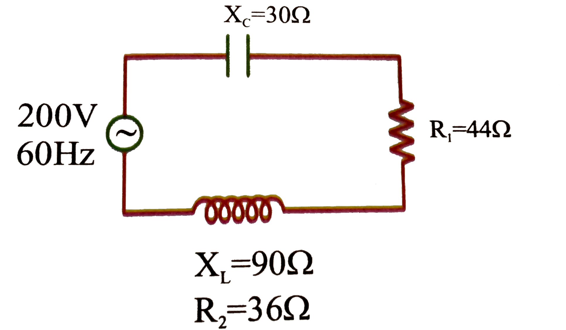
The power used in the circuit isA320WB144WC160WD96WA series circuit connected across a 200V,60Hz line consists of a capacitive reactance 30Ω non inductive resistor of 44Ω and a coil of inductive reactance 90Ω and resistance 36Ω as shown in the diagram

The power dissipated in the inductance coil isAzeroB320WC144WD160WAs given in the figure a series circuit connected across a 200 V, 60 Hz line consists of a capacitor of capacitive reactance 30Ω , a non-inductive resistor 44Ω , a coil of inductive reactance 9012 and another resistance of resistance 36Ω. The power dissipated in the circuit is
 A320 WB176 WC144 WD0 W
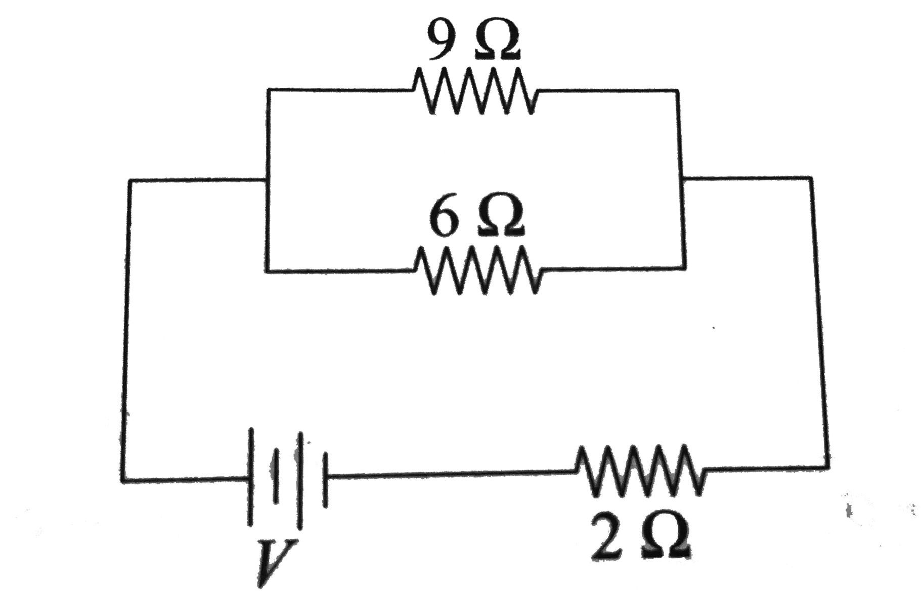
If power dissipated in the 9Ω resistor in the resistor shown is 36W, the potential difference across the 2Ω resistor is

View SolutionAn a.c. circuit contains a resistance of 3Ω and inductive reactance of 4Ω. The cosine of the phase angle between the current and potential difference in this circuit is
View SolutionA 200V ac source is applied in a LCR series circuit which consists of an inductive reactance of 50Ω a capacitive reactance of 50Ω and the resistance of 10Ω The potential difference across the resistance is .
View SolutionA circuit consists of a noniductive resistor of 50Ω, a coil of inductance 0.3H and resistance 2Ω, and a capacitor of 40μF in series and is supplied with 200 volt rms at 50 cycles / sec. Then
View SolutionA coil of inductive reactance 1/√3Ω and resistance 1Ω is connected to a 200V, 50Hz A.C. supply. The time lag between maximum voltage and current is
View Solution
