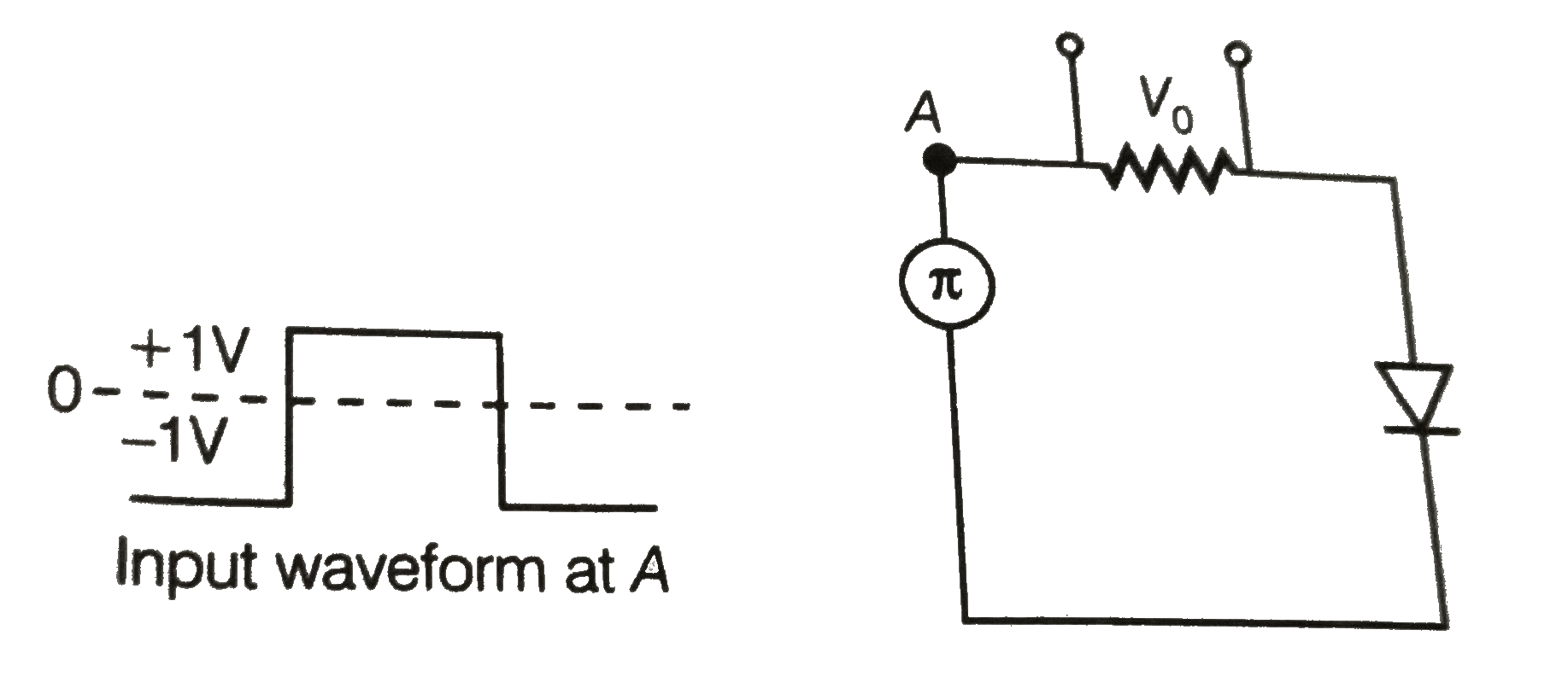
Draw the output waveform across the resistor in the given figure.


The correct Answer is:A
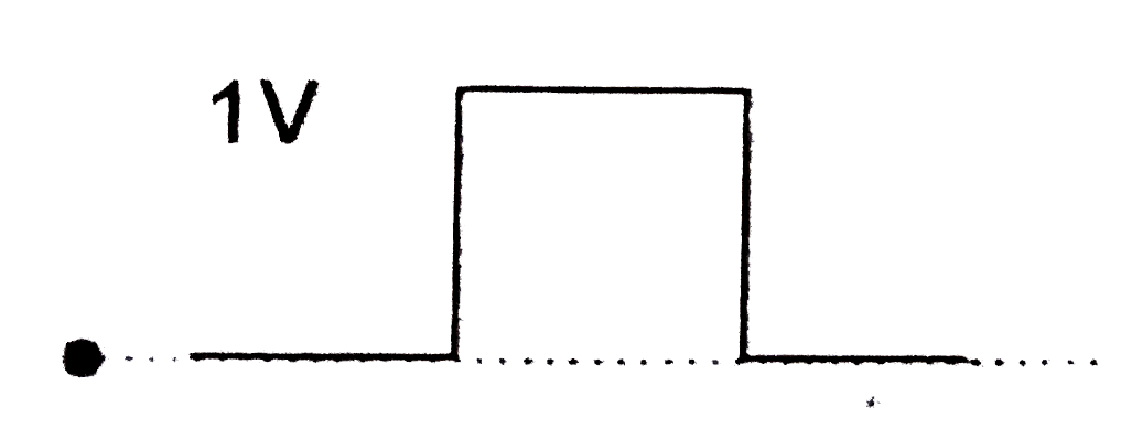
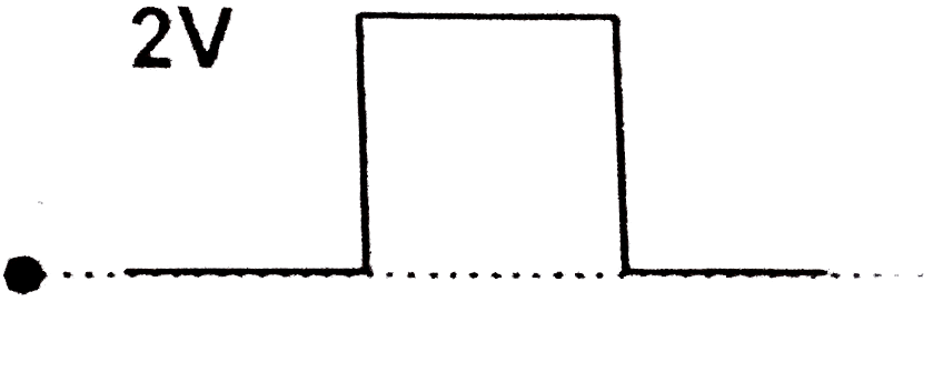
The p−n junction diode acts as a half wave rectifier, so the output waveform across the resistor is positvie half part.
Similar Questions
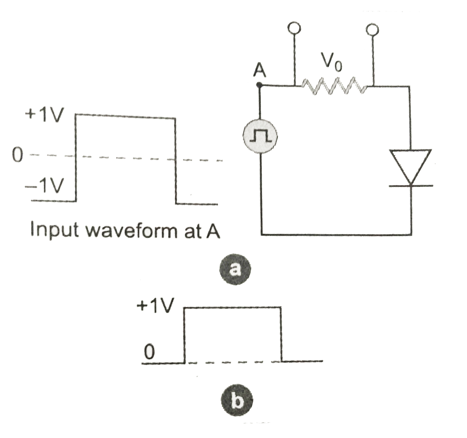
Draw the output waveform across the resistor (Fig.)
View SolutionWhat is an ideal diode ? Draw the output waveform across the load resistor R, If the wavelength is as shown in the figure.
_S01_097_Q01.png)
View Solution

(a) Draw the circuit diagram of reversed bias p-n junction.
(b). Draw the output wavefrom across diode in given circuit.
(c). Draw the truth table for the given logic gate.
View SolutionA square wave (-1 to +1V) is applied to a P-N junction diode as shown. Draw the output wave form across the diode which is assumed to be ideal-
View SolutionAssuming the ideal diode, draw the output waveform for the circuit given in fig. (a), explain the waveform
View SolutionDraw the output waveformed at X, using the given inputs A and B for the logic circuit shows below. Also, identify the logic operation performed by this circuit.

View SolutionDraw the output waveform X, using the given inputs A and B for the logic circuit shows below. Also, identify the logic operation performed by this circuit.

View SolutionThe figure shows the input weveforms A and B for 'AND' gate Draw the output waveform and write the truth table for this logic gate
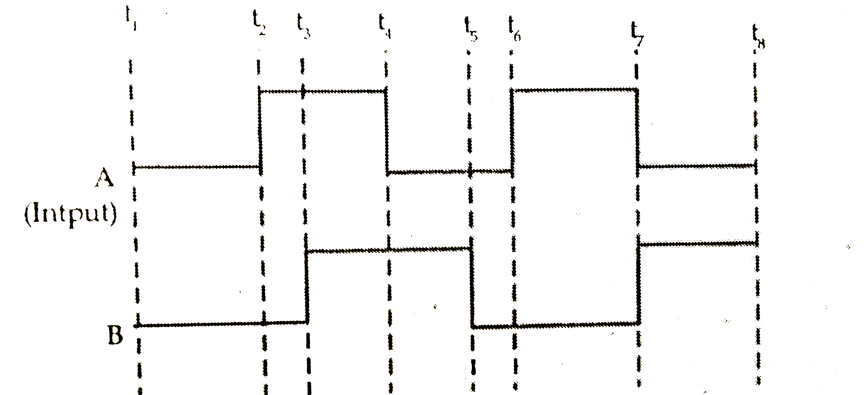 .
.
View SolutionThe Fig shown input waveforms A and B to a logic gate. Draw the output waveform for an OR gate. Write the truth table for this logic gate and draw its logic symbol.
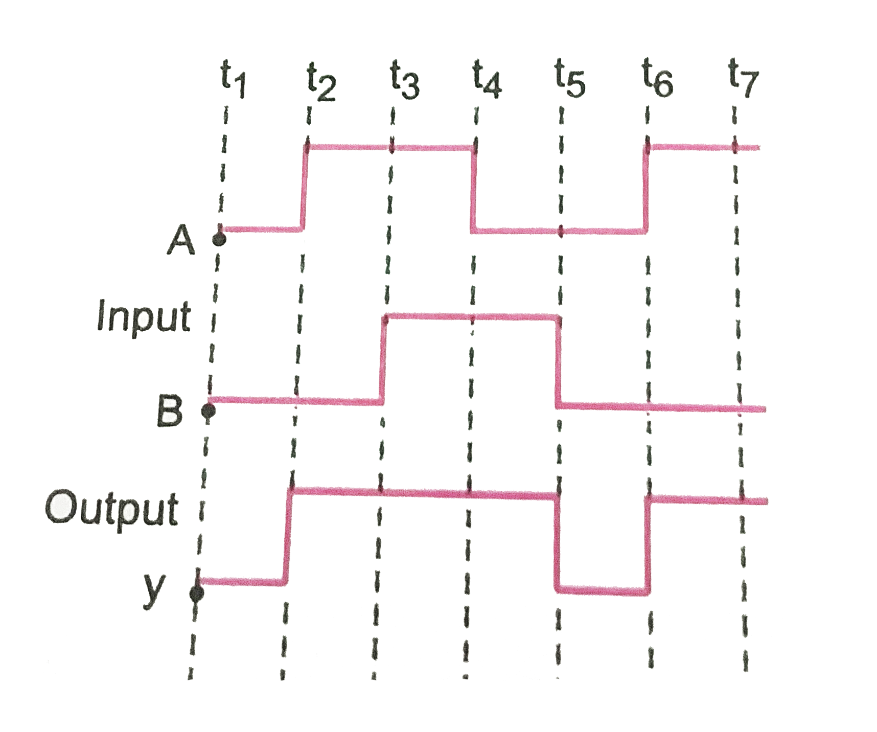
View SolutionThe following Fig. shows the input waveforms (A,B) and the output waveform (y) of a gate. Identify the gate and write its truth table.
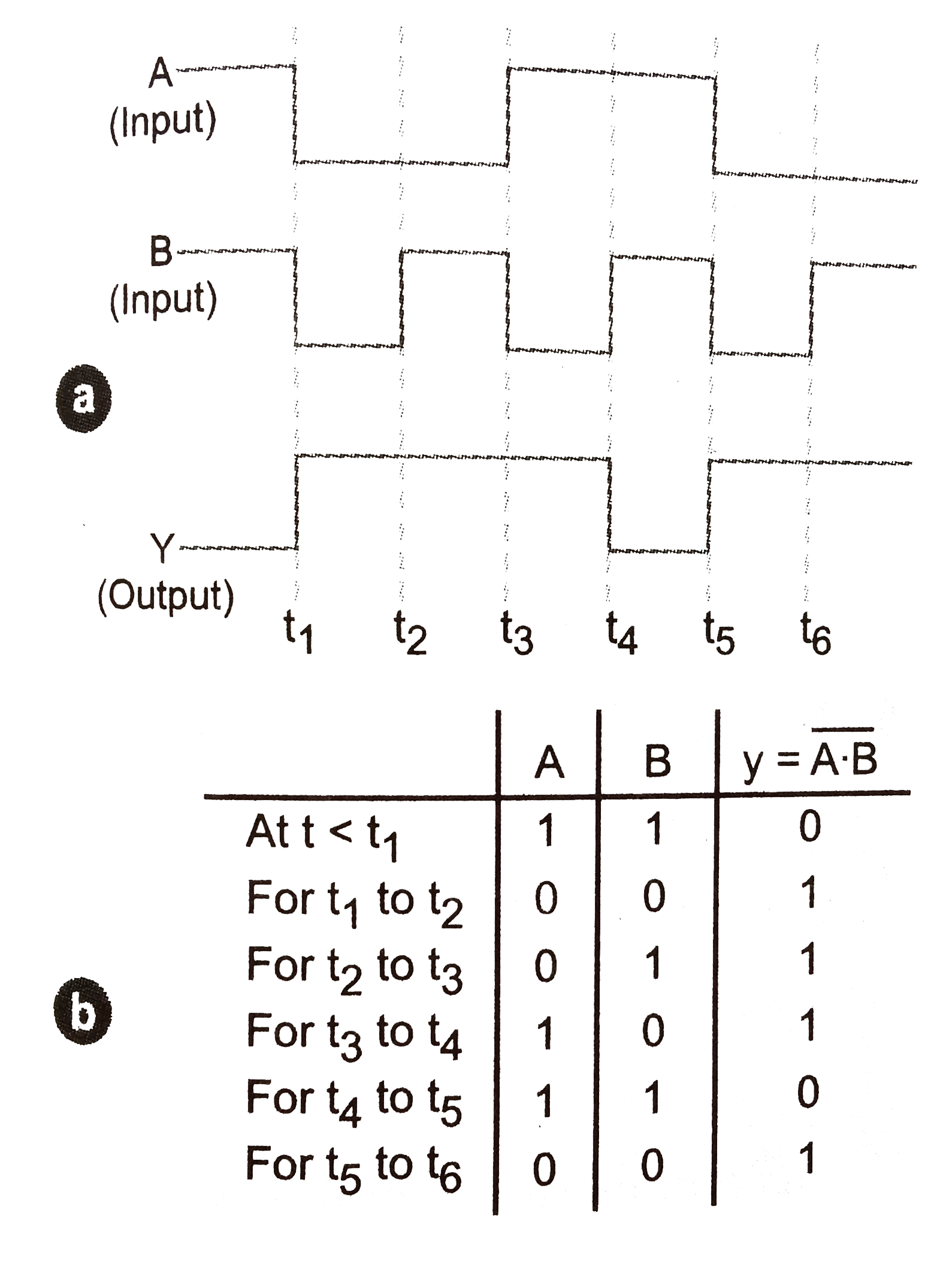
View Solution
