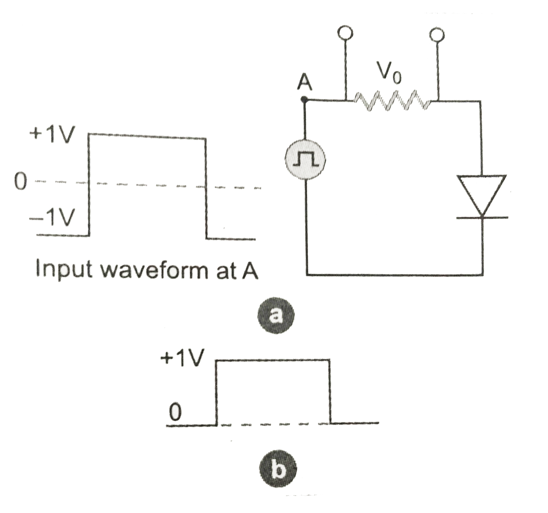
What is an ideal diode ? Draw the output waveform across the load resistor R, If the wavelength is as shown in the figure.
_S01_097_Q01.png)
An ideal diode has zero resistance when forward biased and infiniter resistance when it is reversed biased. Output wave form is shown in figure.
_S01_097_S01.png)
Topper's Solved these Questions
- WAVES AND OSCILLATIONSBOOK - ALLENCHAPTER - WAVES AND OSCILLATIONSEXERCISE - Part-1(Exercise-01)
53 Videos
- WAVES AND OSCILLATIONSBOOK - ALLENCHAPTER - WAVES AND OSCILLATIONSEXERCISE - Part-1(Exercise-02)
19 Videos
- WAVES AND OSCILLATIONSBOOK - ALLENCHAPTER - WAVES AND OSCILLATIONSEXERCISE - Part-2(Example)
15 Videos
- SEMICONDUCTORSBOOK - ALLENCHAPTER - SEMICONDUCTORSEXERCISE - Part-3(Exercise-4)
51 Videos
Similar Questions
Knowledge Check
What is the wavelength of wave shown in given figure ?
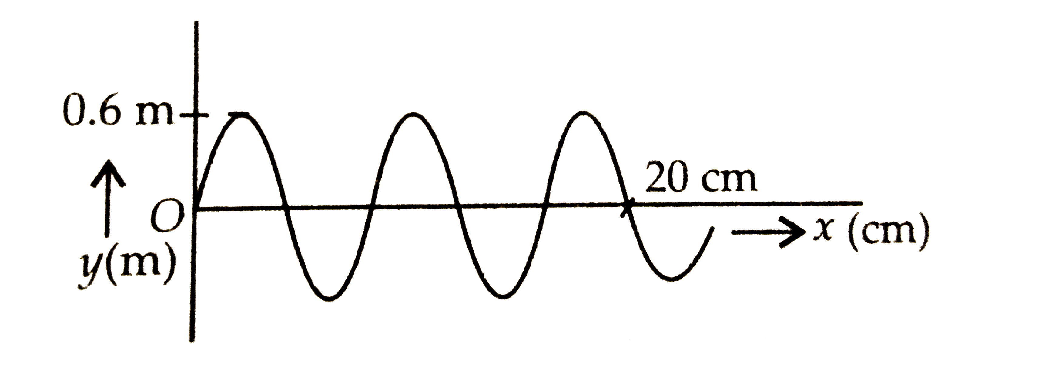 A0.6 mB0.3 mC0.08 mD4 cm
A square wave (-1 to +1V) is applied to a P-N junction diode as shown. Draw the output wave form across the diode which is assumed to be ideal-
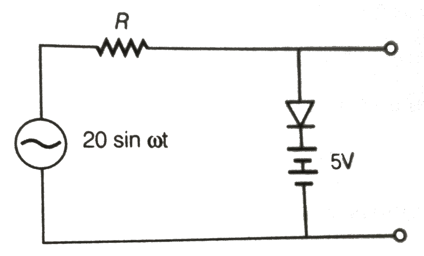
View SolutionAssuming the ideal diode, draw the output waveform for the circuit given in fig. (a), explain the waveform
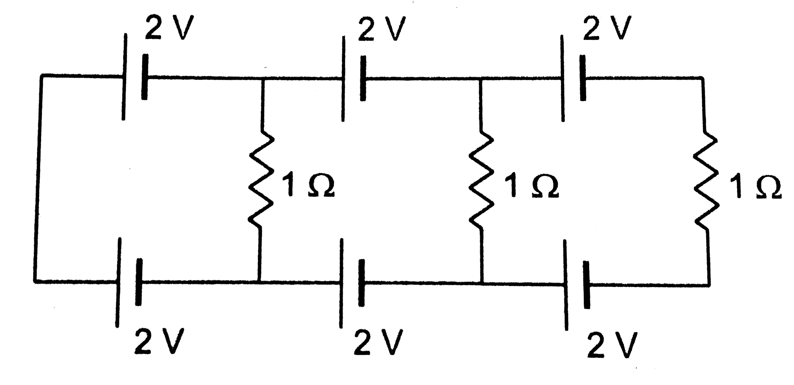
View SolutionFind the current in the resistor shown in figure.
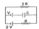
View SolutionIn the circuit shown, tp across the 2R resistor muhe voltage drost be
View SolutionA battery of emf epsilon and internal resistance r is connected across a load resistance RL . The plot between output power and load resistance is shown in the figure. The value of emf epsilon and internal resistance r respectively will
_PHY_E05_112_Q01.png)
View SolutionA battery of emf (epsilon) and internal resistance r is connected across a load resistanvce (RundersetL). The plot between output power and load resistance is shown in the figure.
_PHY_E05_024_Q01.png) value of emf (ε) and internal resistance respectively will be
value of emf (ε) and internal resistance respectively will be
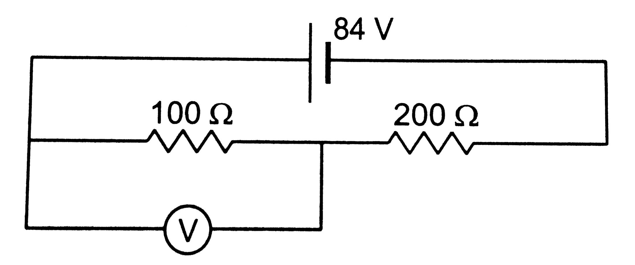
View SolutionA voltmeter of resistances 400(Ω)is used to measure the potential difference across the 100(Ω)resistor in the circuit shown in figure.(a) What will be the reading of the voltmeter ?(b) What was the potential difference across 100(Ω)before the voltmeter was connected ?
View Solution

