A square wave (-1 to +1V) is applied to a P-N junction diode as shown. Draw the output wave form across the diode which is assumed to be ideal-
The correct Answer is:A
Voltage >0 will passed through diode but voltage <0 will be reverse bias the junction Thus, output will be zero.
Topper's Solved these Questions
Similar Questions
Knowledge Check
A sinusoidal voltage of rms value 220 V is applied to a diode and a resistor R in the circuit shown in figure so that half wave rectification occurs. If the diode is ideal, what is the rms voltage across R1?
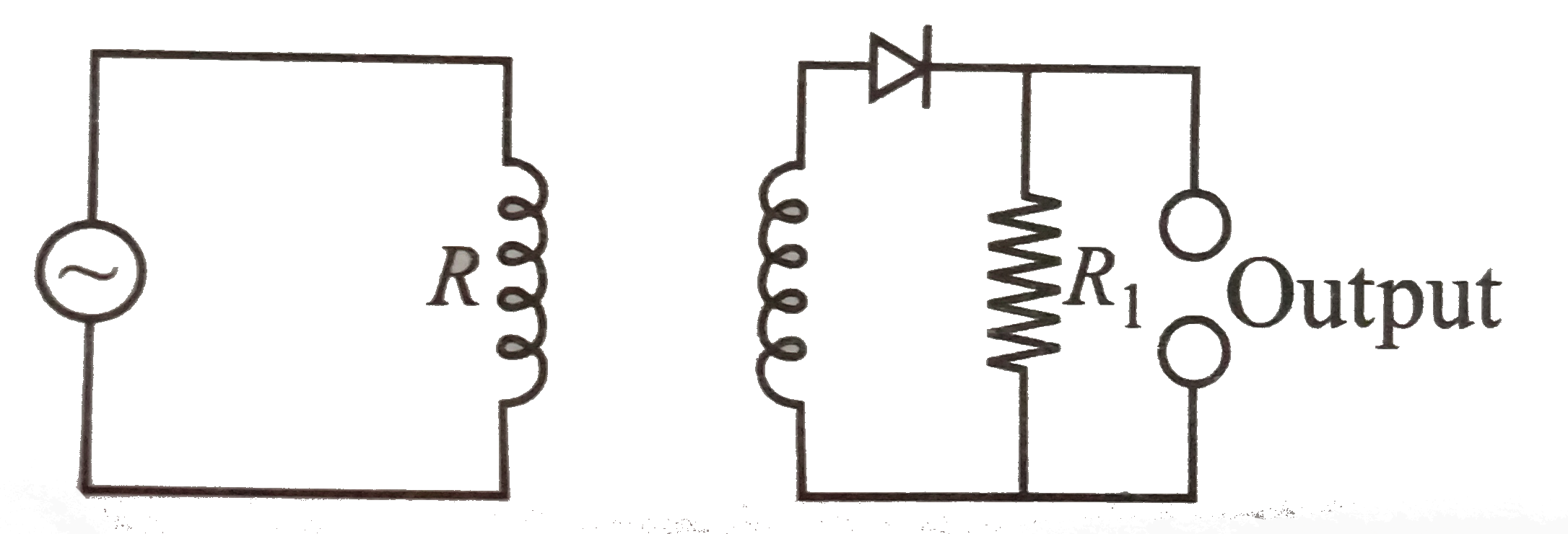 A55√2 VB110 VC110√2 VD220√2 V


(a) Draw the circuit diagram of reversed bias p-n junction.
(b). Draw the output wavefrom across diode in given circuit.
(c). Draw the truth table for the given logic gate.
View SolutionAssuming the ideal diode, draw the output waveform for the circuit given in fig. (a), explain the waveform
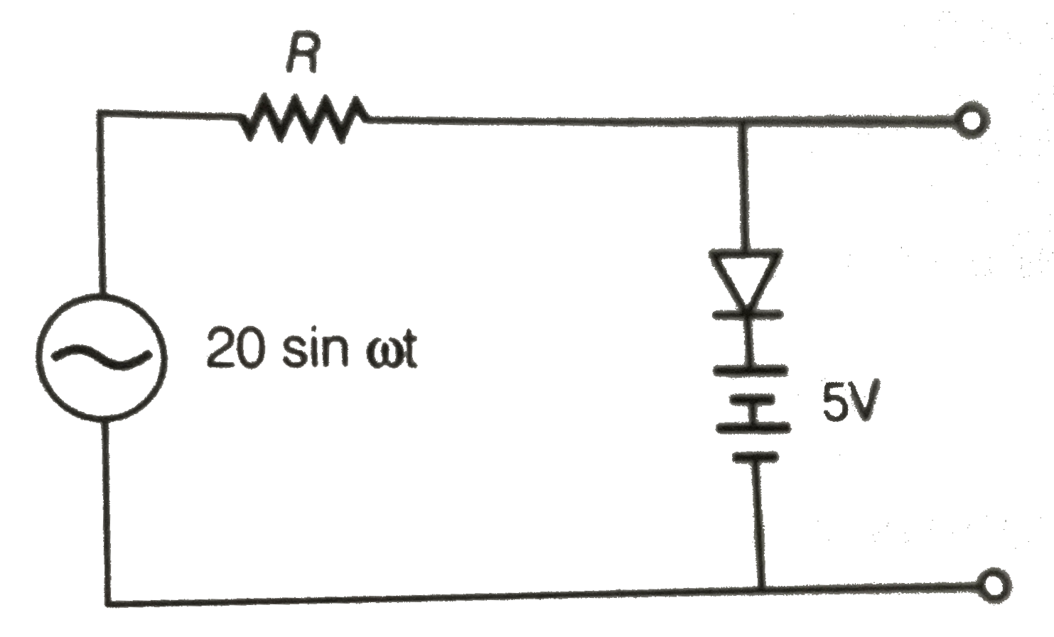
View SolutionFor the given circuit of P-N junction diode which is correct : -

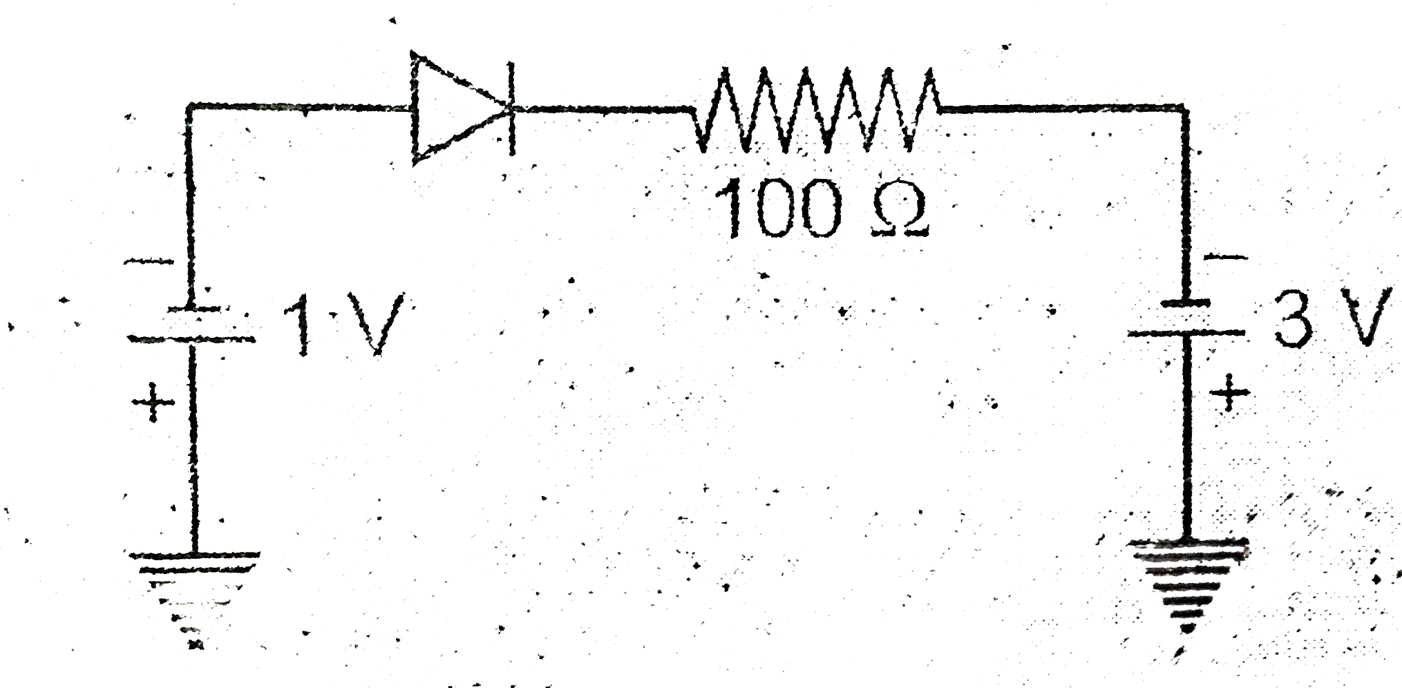
View SolutionWhat is the current through an ideal p-n junction diode shown in figure below ?
View SolutionA P−N junction diode can withstand currents up to 10mA. Under forward bias, The diode has a potential drop of 0.5V across it which is assumed to be independent of current. The maximum voltage of the battery used to forward bias the diode when a resistance of 200Ω is connected in series with it is
View SolutionIf a p−n junction diode, a square input signal of 10V is applied as shown.
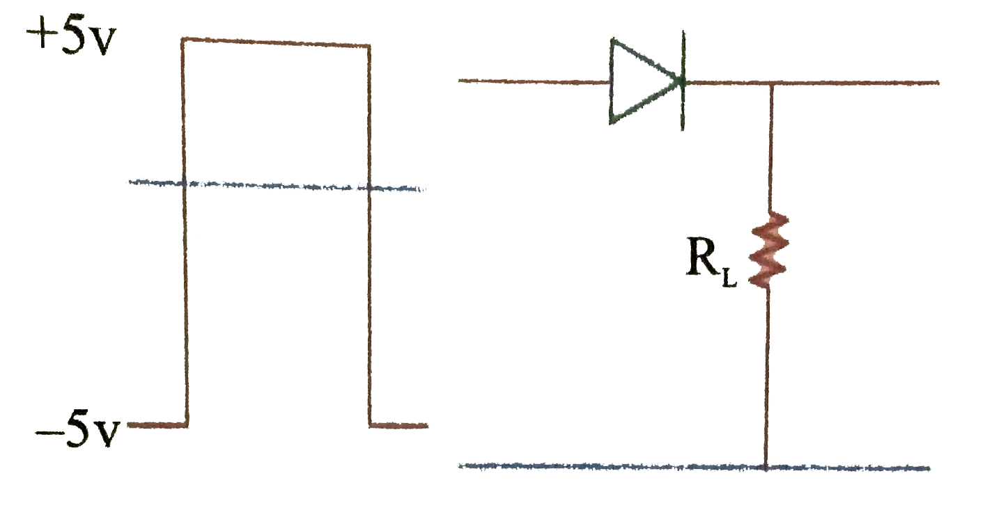
Then the out put signal across RL will be
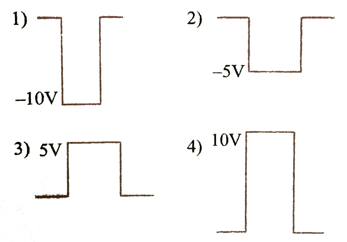 .
.
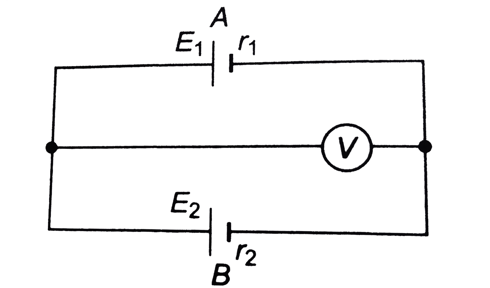
View SolutionTwo cells A and B of emf 1.3V and 1.5Vrespectively are arranged as shown in figure. The voltmeter reds 1.45V. The voltmeter is assumed to be ideal. Then
View Solution


_S01_097_Q01.png)