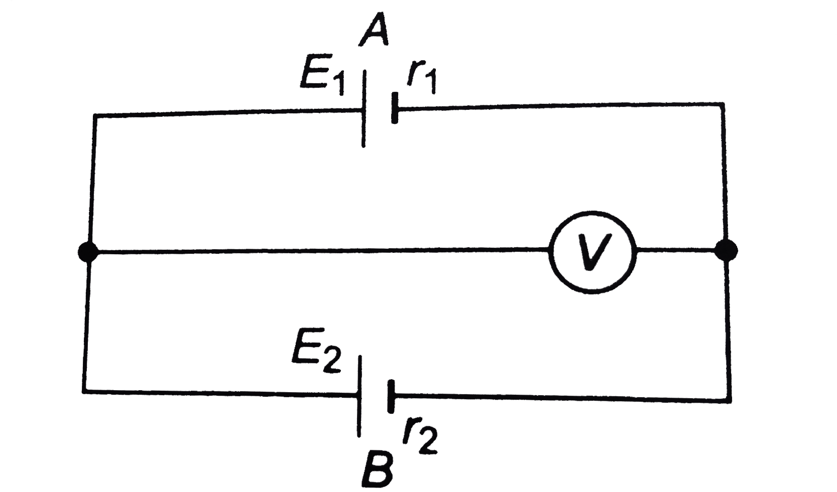
Two cells A and B of emf 1.3V and 1.5Vrespectively are arranged as shown in figure. The voltmeter reds 1.45V. The voltmeter is assumed to be ideal. Then
r1=2r2
r1=3r1−2
r2=2r1
r2=3r1
The correct Answer is:B
No current will flow through voltmeter. As it is ideal (infinite resistance). Current through two batteries
i=1.5−1.3r1+r2=0.2r1+r2
Now, V=E2−ir2
∴1.45=1.5−(0.2r1+r2)(r2)
Solving this equation we get r1=3r2
Topper's Solved these Questions
- CURRENT ELECTRICITYBOOK - DC PANDEY ENGLISHCHAPTER - CURRENT ELECTRICITYEXERCISE - Level 2 More Than One Correct
10 Videos
- CURRENT ELECTRICITYBOOK - DC PANDEY ENGLISHCHAPTER - CURRENT ELECTRICITYEXERCISE - Level 2 Comprehension Example Type
2 Videos
- CURRENT ELECTRICITYBOOK - DC PANDEY ENGLISHCHAPTER - CURRENT ELECTRICITYEXERCISE - Level 1 Subjective
53 Videos
- COMMUNICATION SYSTEMBOOK - DC PANDEY ENGLISHCHAPTER - COMMUNICATION SYSTEMEXERCISE - Subjective
11 Videos
- ELECTROMAGNETIC INDUCTIONBOOK - DC PANDEY ENGLISHCHAPTER - ELECTROMAGNETIC INDUCTIONEXERCISE - Medical entrances gallery
25 Videos
Similar Questions
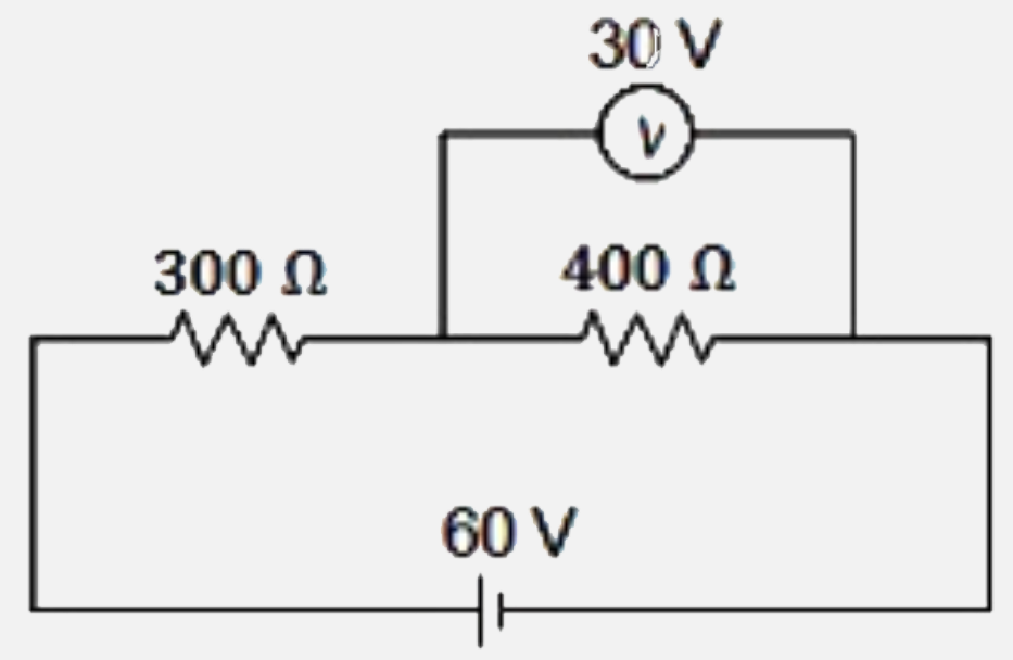
In the circuit figure, the voltmeter reads 30 V. The resistance of the voltmeter is
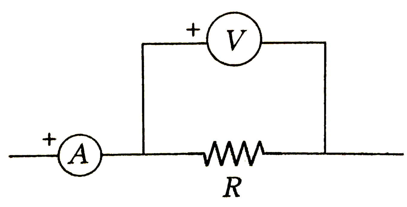
View SolutionAn ammeter A, a voltmeter V and a resistance R are connected as shown in the figure. If the voltmeter reading is 1.6V and the ammeter reading is 0.4A, then R is
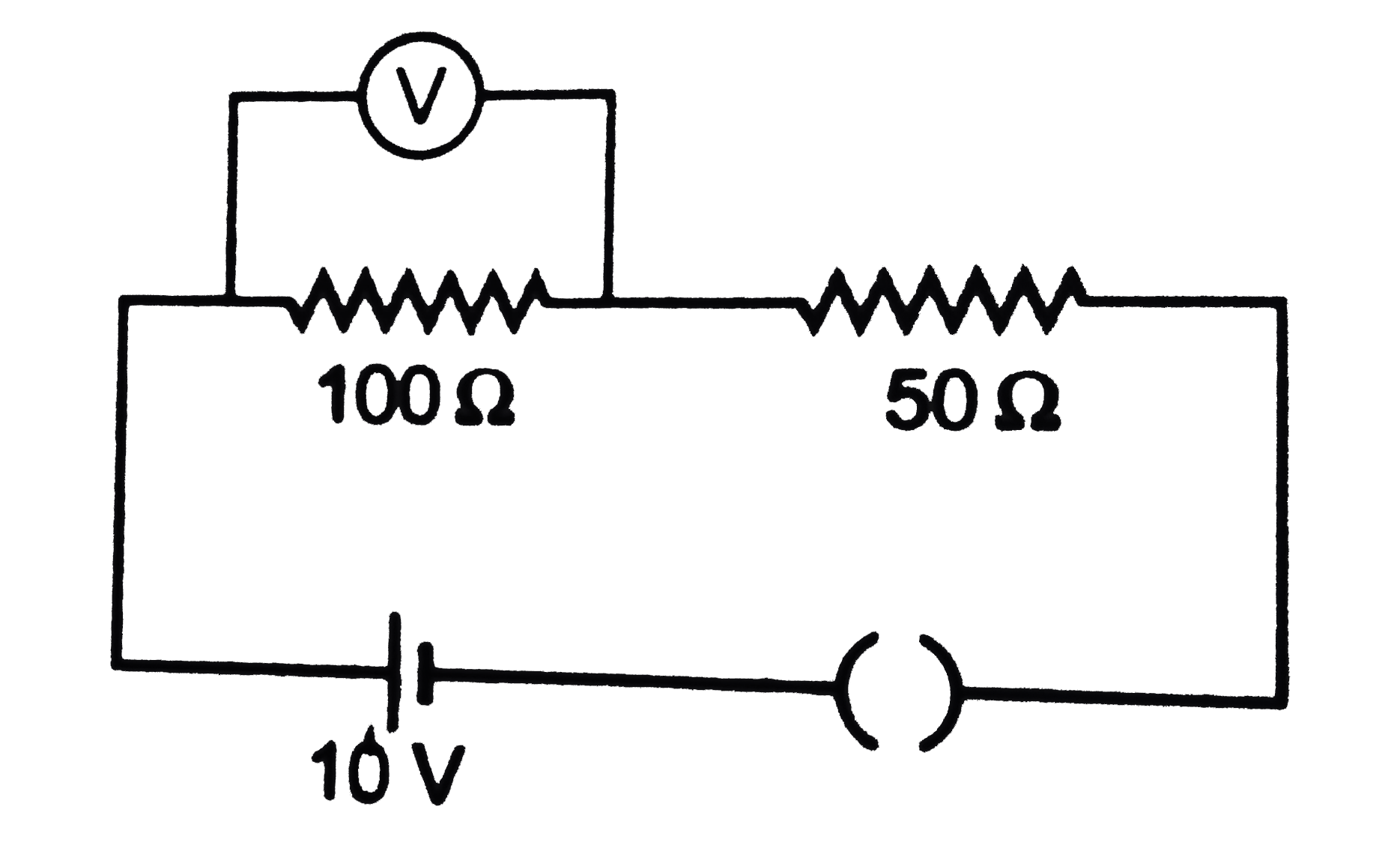
View SolutionIn the given circuit, the voltmeter records 5 V. The resistance of the voltmeter in Ω is
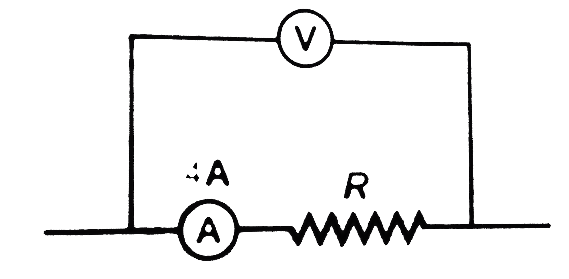
View SolutionA students connects an ammeter Aand a voltmeter V to measure a resistancer as shown in figure. If the voltmeter reads 20V and the ammeter reads 4A, then R is
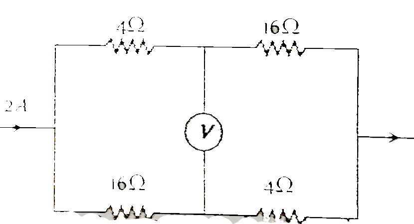
View SolutionIn the circuit shown below. The reading of the voltmeter V is
View SolutionAn ideal voltmeter V and ideal ammeter A are connected in a circuit as shown in the figure. If the reading of the voltmeter is 32 V, the reading of ammeter will be
View SolutionWhen key K is open in a circuit as shown in figure, an ideal voltmeter reads 1.53 V. If key is closed then ideal ammeter reads 1A and voltmeter reads 1.03 V. Then EMF of cell and external resistance R are respectively
View SolutionIn the circuit shown, A and V are ideal ammeter and voltmeter respectively. Reading of the voltmeter will be

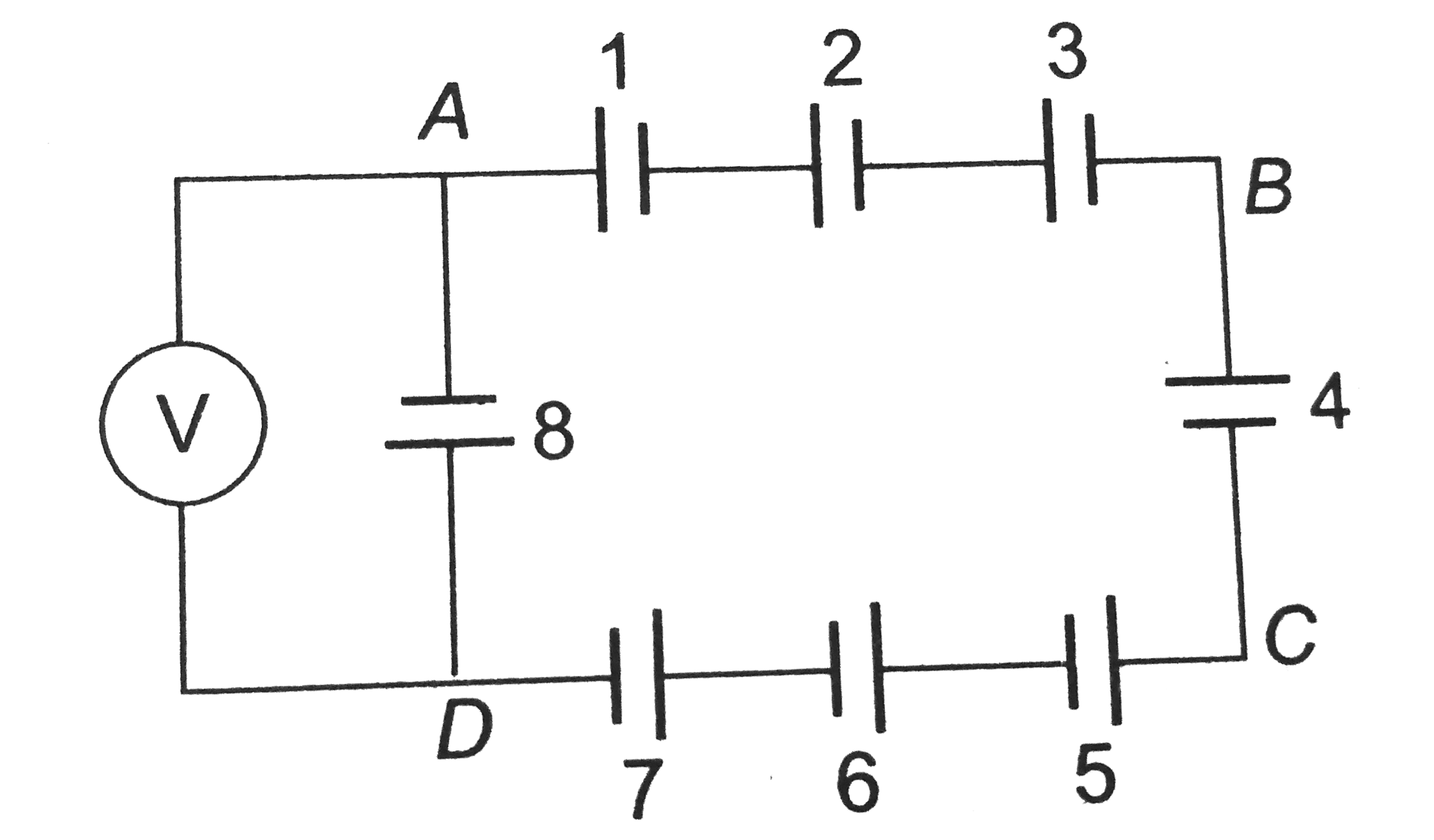
View SolutionEight cells marked 1 to 8, each of emf 5V and internal resistance 0.2Ω are connected as shown. What is the reading of ideal voltmeter ?
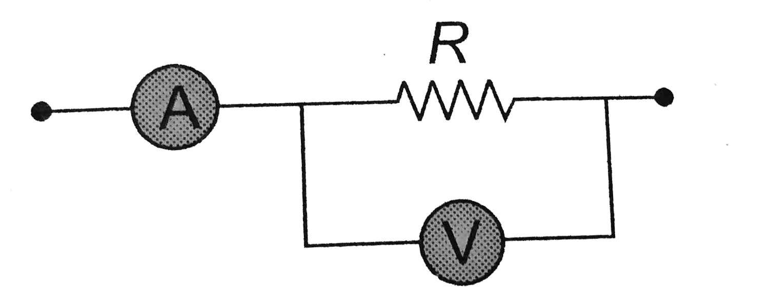
View SolutionIn the circuit shown the reading of ammeter and voltmeter are 4A and 20V respectively. The meters are non ideal, then R ia
View Solution
