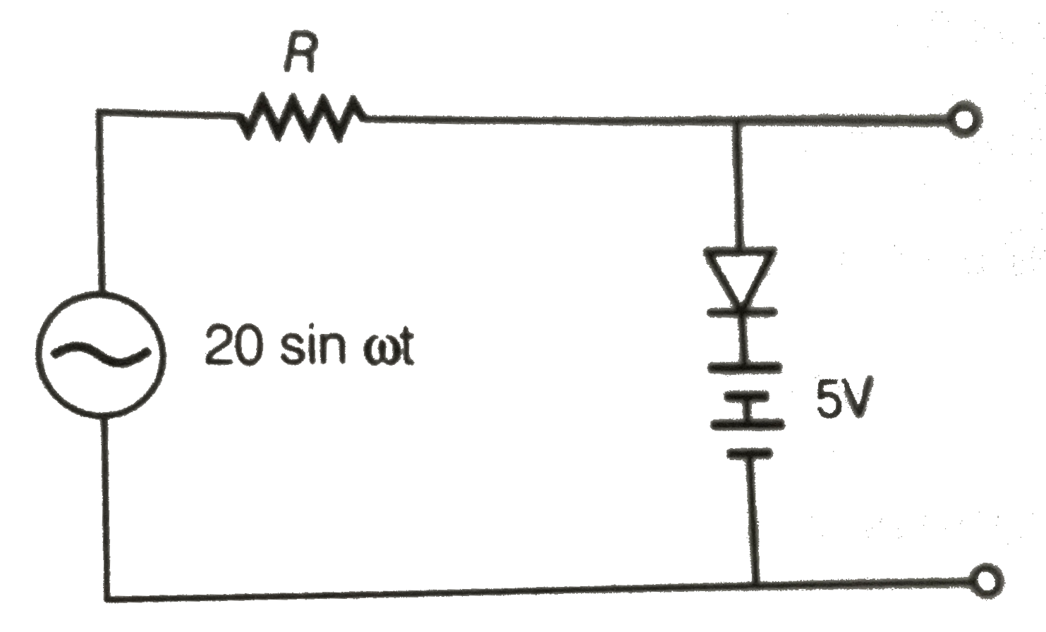
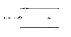
Assuming the ideal diode, draw the output waveform for the circuit given in fig. (a), explain the waveform
Video Solution
Text Solution
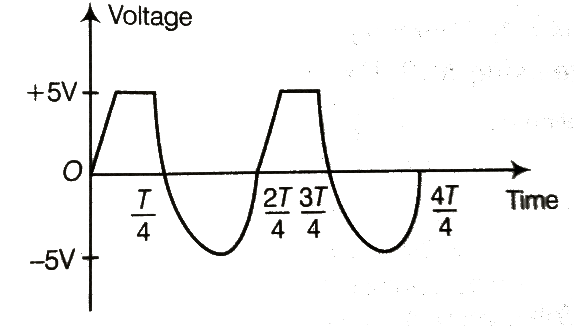
When the input voltage is equal to or less than 5V, diode will be revers biased. It will offer high resistance in comparison to resistance (R) in series. Now, diode appears in open circuit. The input waveform is then passed to the output terminals. The result with sin wave input is to dip off all positive going portion above 5V.
If input voltage is more than +5V, diode will be conducting as if forward biased offering low resistance in comparison to R. But there will be no voltage in output beyond 5V as the voltage beyond +5V will appear across R.
When input voltage is negative, there will be oppositive to 5V battery in p−n junction input voltage becomes more than −5V, the diode will be reverse biased. It will offer high resistance in comparison to resistance R in series. Now junction diode appears in open circuit. The input wave form is then passed on the output terminals.
|
Topper's Solved these Questions
- NUCLEIBOOK - NCERT EXEMPLAR ENGLISHCHAPTER - NUCLEIEXERCISE - Very short Anwer type question
14 Videos
- MOVING CHARNGES AND MAGNETISMBOOK - NCERT EXEMPLAR ENGLISHCHAPTER - MOVING CHARNGES AND MAGNETISMEXERCISE - Long Answer Type Questions
7 Videos
- RAY OPTICS AND OPTICAL INSTRUMENTS BOOK - NCERT EXEMPLAR ENGLISHCHAPTER - RAY OPTICS AND OPTICAL INSTRUMENTS EXERCISE - VERY SHORT ANSWER TYPE QUESTIONS
16 Videos
Similar Questions
Knowledge Check
The output of the given circuit in figure given below,
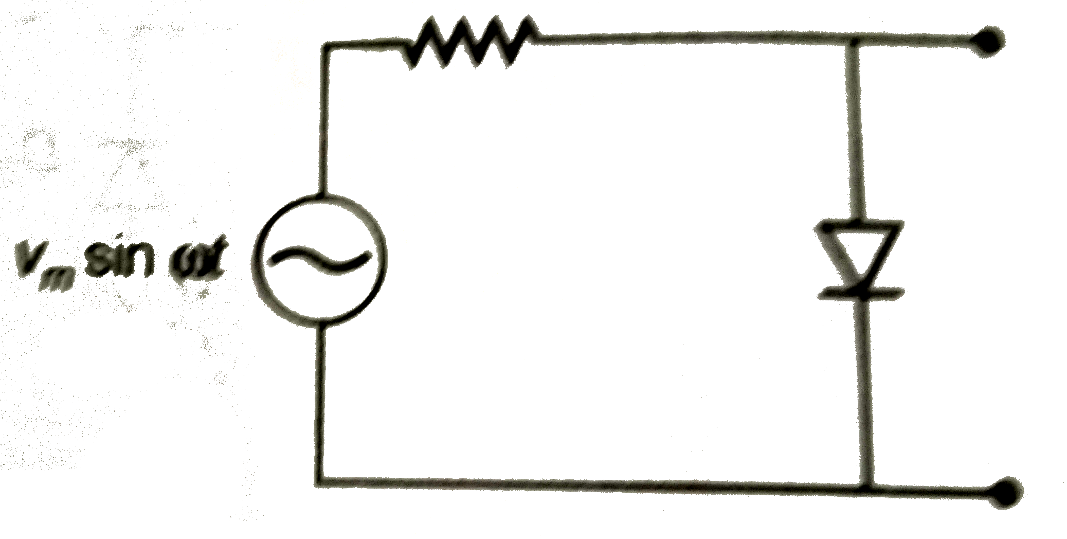 Awould be zero at all times.Bwould be like a half wave rectifier with positive cycles in outputCwould be like a half wave rectifier with negative cycles in output.Dwould be like that of a full wave rectifier.
Draw the output waveform across the resistor (Fig.)
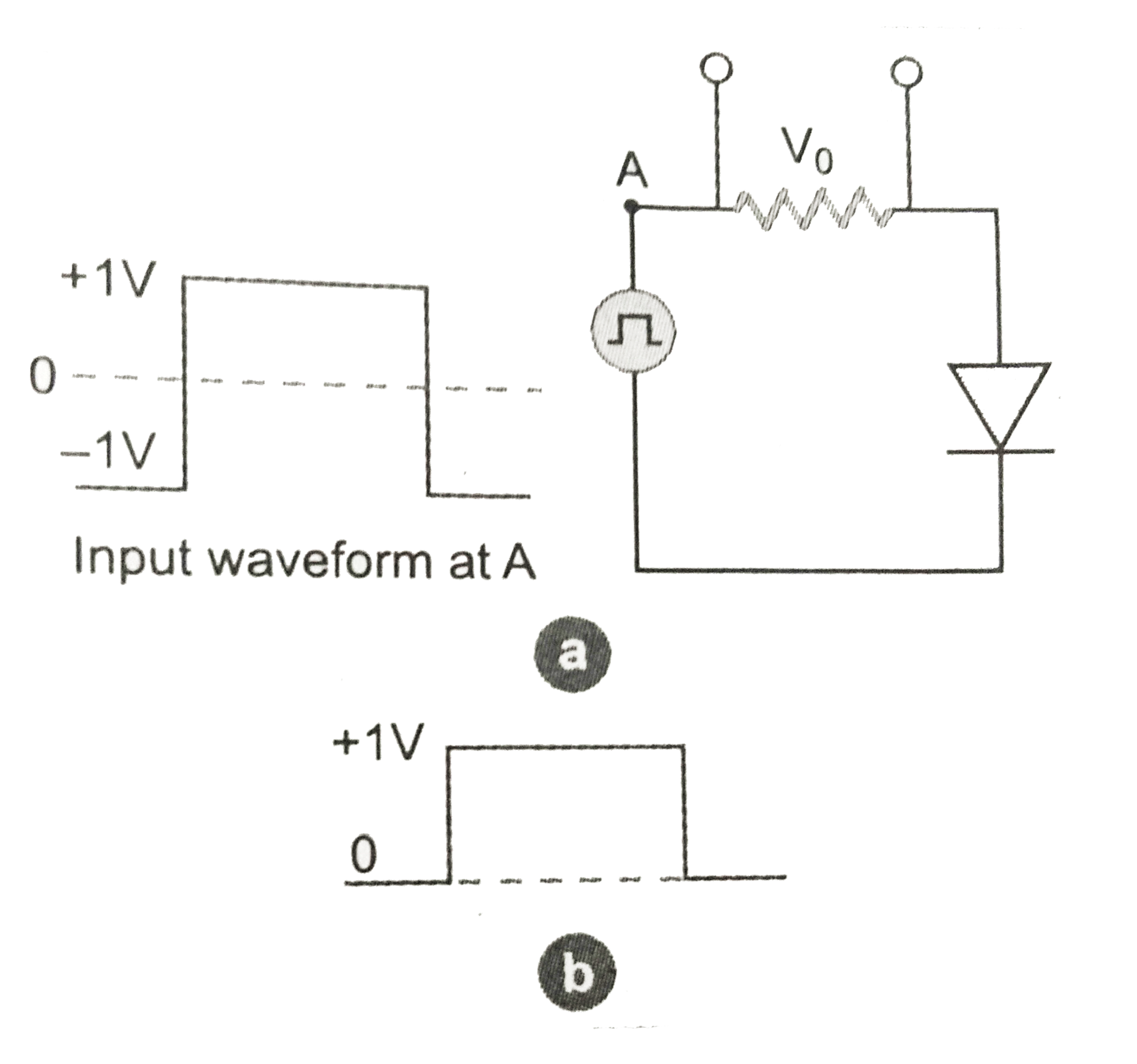
View SolutionThe output of the given circuit in figure:
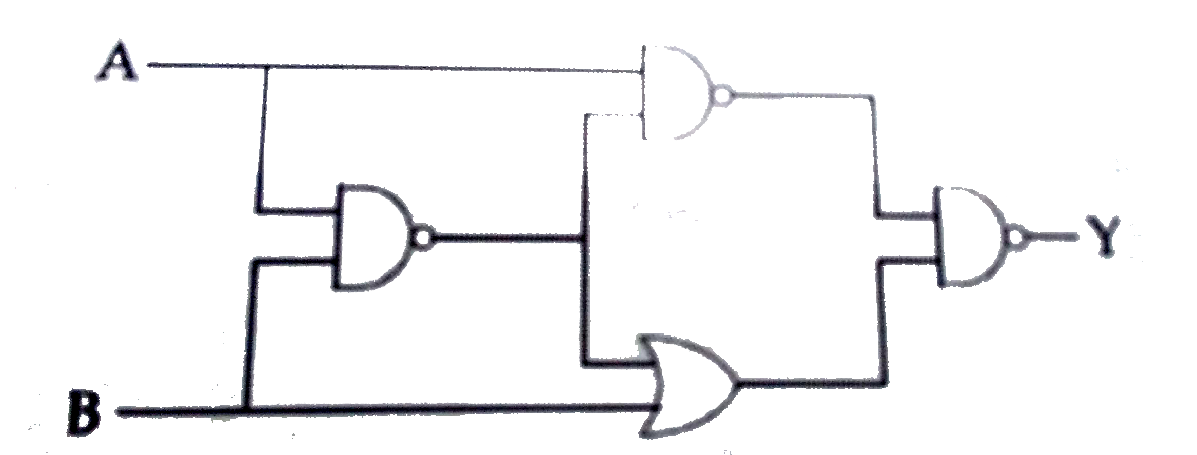
View Solutionthe output given logic circuit is :
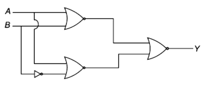
View SolutionThe output of the given logic circuit is
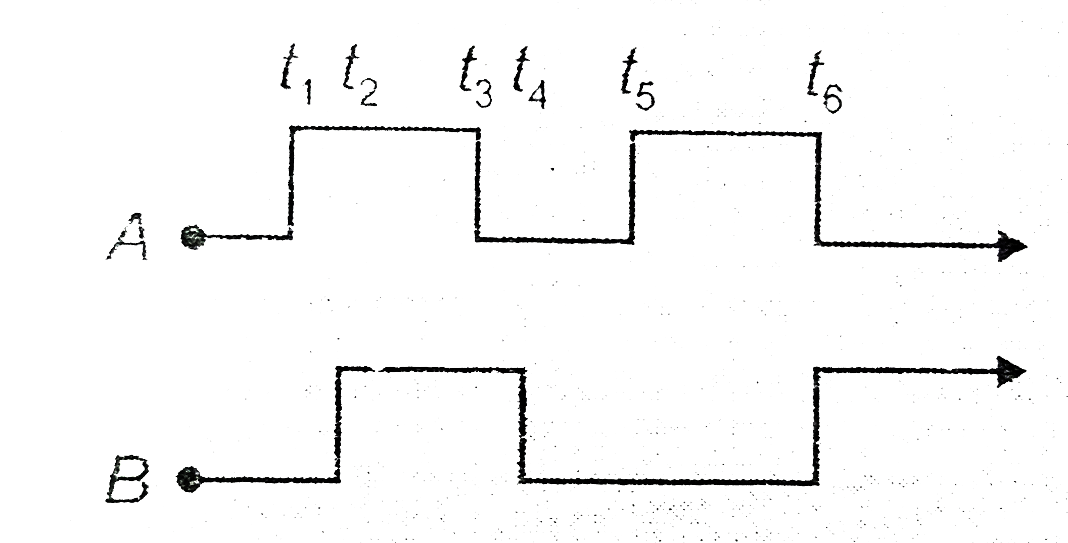
View SolutionShow the output waveform of OR gate for the following input waveforms of A and B

View SolutionShow the output waveform of OR gate for the following input waveforms of A and B
View SolutionThe output of the given circuit in figure given below,

View Solution


