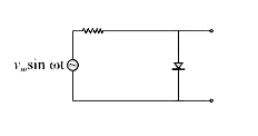
The output of the given circuit in figure:
A
would be zero at all times.
B
would be like a half wave rectifier with positive cycles in output.
C
would be like a half wave rectifier with negative cycles in output.
D
would be like that of a full wave rectifier.
Video Solution
Text Solution
The correct Answer is:C
It is half wave rectifier, if diode conducts then no output (as no drop across it) during negative half cycles Vout=Vmsinωt.
|
Topper's Solved these Questions
- JEE MAIN REVISION TEST - 18BOOK - VMC MODULES ENGLISHCHAPTER - JEE MAIN REVISION TEST - 18EXERCISE - PHYSICS - SECTION 2
5 Videos
- JEE MAIN REVISION TEST - 13BOOK - VMC MODULES ENGLISHCHAPTER - JEE MAIN REVISION TEST - 13EXERCISE - PHYSICS (SECTION 2)
5 Videos
- JEE MAIN REVISION TEST - 19BOOK - VMC MODULES ENGLISHCHAPTER - JEE MAIN REVISION TEST - 19EXERCISE - PHYSICS
25 Videos
Similar Questions
The output for the given, circuit is

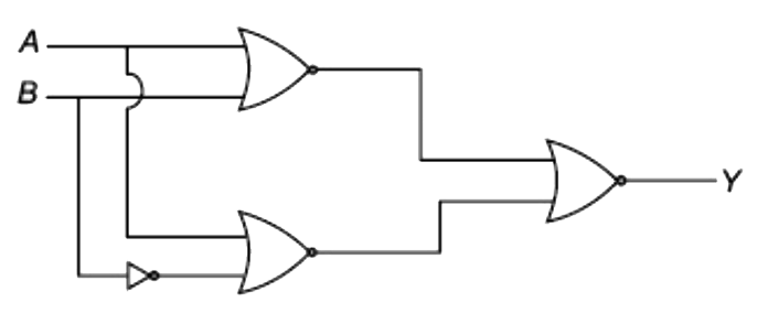
View SolutionThe output of the given logic circuit is
View SolutionThe output of the given logic gate is

View SolutionThe output of the given logica gate is

View Solution_2019_CBT4_E01_066_Q01.png)
The output of the given combination of gates is equivalent to:
View Solutionthe output given logic circuit is :
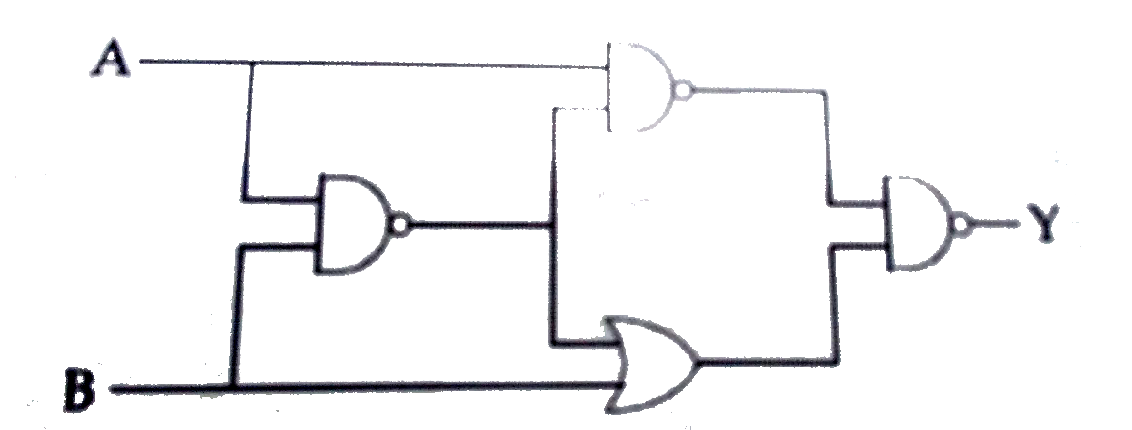
View SolutionFor the circuit shown in figure
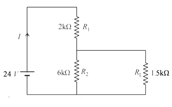
View SolutionThe output (X) of the logic circuit shown in figure will be

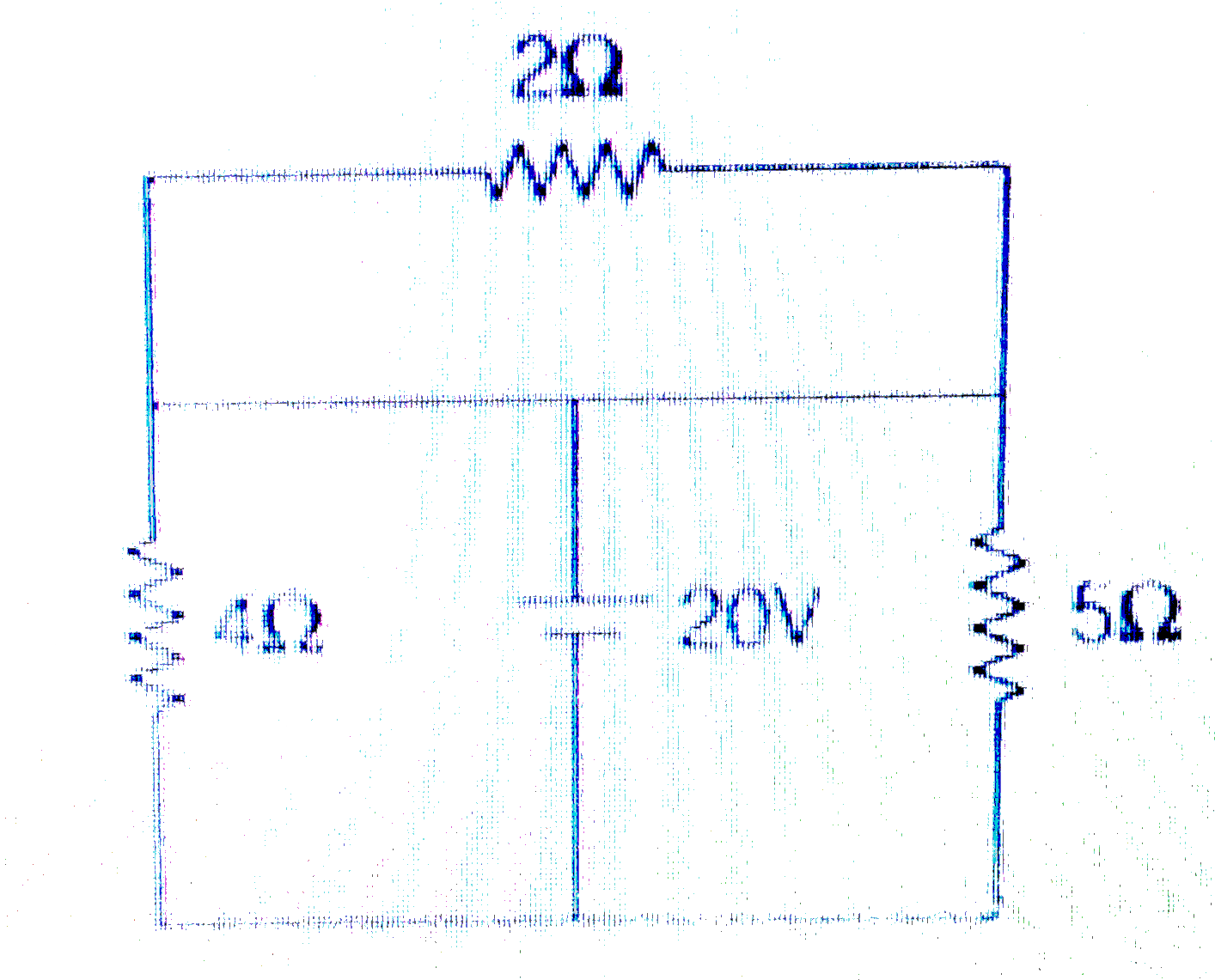
View SolutionIn the circuit shown in figure
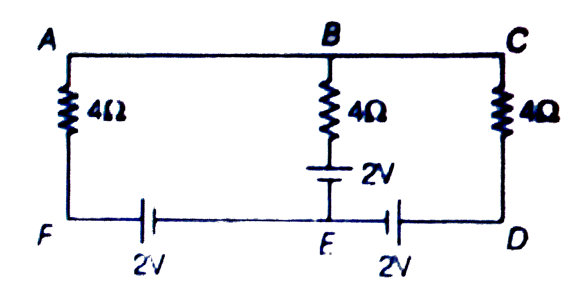
View SolutionIn the circuit shown in figure
View Solution
