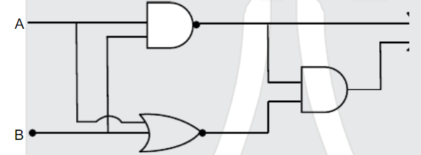
An X-OR gate has following truth table:
It is represented by following logic relation
y=¯¯¯A.B+A.¯¯¯B
Build this gate using AND, OR and NOT gates.
∣∣
∣
∣
∣
∣
∣∣ABY000011101110∣∣
∣
∣
∣
∣
∣∣
To build an XOR gate using AND, OR, and NOT gates based on the provided logic relation Y=¯¯¯¯AB+A¯¯¯¯B, we can follow these steps:
Step 1: Identify Inputs
We have two inputs, A and B.
Step 2: Create NOT Gates
1. NOT Gate for A: We need to create ¯¯¯¯A. Connect input A to a NOT gate.
2. NOT Gate for B: We need to create ¯¯¯¯B. Connect input B to another NOT gate.
Step 3: Create AND Gates
1. AND Gate for ¯¯¯¯AB: Take the output from the NOT gate for A (which is ¯¯¯¯A) and connect it to one input of an AND gate. Connect input B to the other input of this AND gate. The output will be ¯¯¯¯AB.
2. AND Gate for A¯¯¯¯B: Take the output from the NOT gate for B (which is ¯¯¯¯B) and connect it to one input of another AND gate. Connect input A to the other input of this AND gate. The output will be A¯¯¯¯B.
Step 4: Create OR Gate
1. OR Gate: Connect the outputs of the two AND gates to an OR gate. The output of this OR gate will be Y, which is Y=¯¯¯¯AB+A¯¯¯¯B.
Final Circuit Diagram
- Inputs: A and B
- Outputs: Y
- Components:
- Two NOT gates (for A and B)
- Two AND gates (for ¯¯¯¯AB and A¯¯¯¯B)
- One OR gate (to combine the outputs of the two AND gates)
Summary of Connections
1. A → NOT gate → ¯¯¯¯A
2. B → NOT gate → ¯¯¯¯B
3. ¯¯¯¯A and B → AND gate → Output 1: ¯¯¯¯AB
4. A and ¯¯¯¯B → AND gate → Output 2: A¯¯¯¯B
5. Output 1 and Output 2 → OR gate → Final Output Y
We have two inputs, A and B.
1. NOT Gate for A: We need to create ¯¯¯¯A. Connect input A to a NOT gate.
2. NOT Gate for B: We need to create ¯¯¯¯B. Connect input B to another NOT gate.
1. AND Gate for ¯¯¯¯AB: Take the output from the NOT gate for A (which is ¯¯¯¯A) and connect it to one input of an AND gate. Connect input B to the other input of this AND gate. The output will be ¯¯¯¯AB.
2. AND Gate for A¯¯¯¯B: Take the output from the NOT gate for B (which is ¯¯¯¯B) and connect it to one input of another AND gate. Connect input A to the other input of this AND gate. The output will be A¯¯¯¯B.
1. OR Gate: Connect the outputs of the two AND gates to an OR gate. The output of this OR gate will be Y, which is Y=¯¯¯¯AB+A¯¯¯¯B.
- Inputs: A and B
- Outputs: Y
- Components:
- Two NOT gates (for A and B)
- Two AND gates (for ¯¯¯¯AB and A¯¯¯¯B)
- One OR gate (to combine the outputs of the two AND gates)
1. A → NOT gate → ¯¯¯¯A
2. B → NOT gate → ¯¯¯¯B
3. ¯¯¯¯A and B → AND gate → Output 1: ¯¯¯¯AB
4. A and ¯¯¯¯B → AND gate → Output 2: A¯¯¯¯B
5. Output 1 and Output 2 → OR gate → Final Output Y
Topper's Solved these Questions
- NUCLEIBOOK - NCERT EXEMPLAR ENGLISHCHAPTER - NUCLEIEXERCISE - Very short Anwer type question
14 Videos
- MOVING CHARNGES AND MAGNETISMBOOK - NCERT EXEMPLAR ENGLISHCHAPTER - MOVING CHARNGES AND MAGNETISMEXERCISE - Long Answer Type Questions
7 Videos
- RAY OPTICS AND OPTICAL INSTRUMENTS BOOK - NCERT EXEMPLAR ENGLISHCHAPTER - RAY OPTICS AND OPTICAL INSTRUMENTS EXERCISE - VERY SHORT ANSWER TYPE QUESTIONS
16 Videos
Similar Questions
Given truth table is related with :-
ABY110011101001
View SolutionThe truth table given below is for :-
ABY001010100111
View SolutionThe following truth table corresponds to the logic gate
∣∣ ∣ ∣ ∣ ∣ ∣∣ABX000011101111∣∣ ∣ ∣ ∣ ∣ ∣∣
View SolutionThe given truth table relates Y to A and B.
ABY001010100110
Then, Y is given by
View SolutionGiven the following truth table where A , B are inputs and Y the output :
ABY001101011110
The output Y is :
View SolutionThe following truth table belongs to which one of the following four gates?
∣∣ ∣ ∣ ∣ ∣ ∣∣ABC110100010001∣∣ ∣ ∣ ∣ ∣ ∣∣
View SolutionA gate has the following truth table
P 1 1 0 0Q 1 0 1 0R 1 0 0 0
The gate is
View Solution
(A,B) IS (0,0), (0,1), (1,0),(1,1) THEN Output at X will be
View SolutionThe transformation due of reflection of (x,y) through the origin is described by the matrix (A) [0000] (B) [1001] (C) [100−1] (D) [0−1−10]
View SolutionWhich of the following matrices have eigen values as 1 and -1 ? (a) [0110] (b) [0110] (c) [100−1] (d) [1001]
View Solution
