Determine to charge on the capacitor in the following circuit :

200μC
60μC
2μC
10μC
The correct Answer is:A
Eeq=6+12×412+4=9Ω∴imain=729=8 amp
therforei10Ω=412+4×8=2amp. ∴Q=CV=10×10−6×(10×2)=200μC.
Topper's Solved these Questions
- CAPACITORSBOOK - VMC MODULES ENGLISHCHAPTER - CAPACITORSEXERCISE - JEE Advance ( Archive ) LEVEL 2
1 Videos
- CAPACITORSBOOK - VMC MODULES ENGLISHCHAPTER - CAPACITORSEXERCISE - JEE Advance ( Archive ) LEVEL 3
1 Videos
- CAPACITORSBOOK - VMC MODULES ENGLISHCHAPTER - CAPACITORSEXERCISE - LEVEL 2
40 Videos
- BASIC MATHEMATICS & VECTORSBOOK - VMC MODULES ENGLISHCHAPTER - BASIC MATHEMATICS & VECTORSEXERCISE - Impeccable
50 Videos
- CURRENT ELECTRICITYBOOK - VMC MODULES ENGLISHCHAPTER - CURRENT ELECTRICITYEXERCISE - IN-CHAPTER EXERCISE-F
10 Videos
Similar Questions
Find the charge and energy stored on the capacitor C in the following circuit.
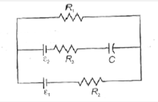
View Solution_2019_CBT3_E01_052_Q01.png)
Determine the charge on capacitor in steady state:
View SolutionThe charge on the capacitor in steady state in the circuit shown is
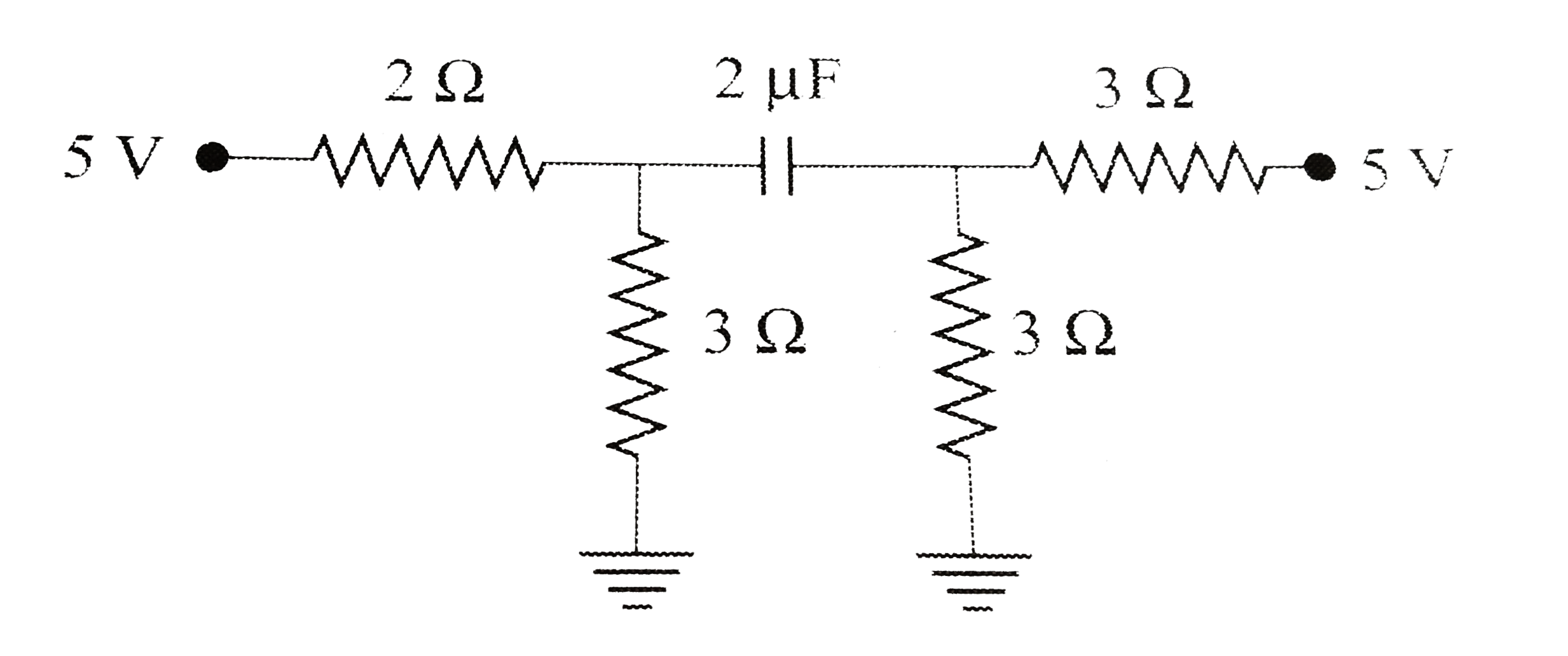
View SolutionA capacitor is charged to a certain potential and then allowed to discharge through a resistance R. The ratio of charge on the capacitor to current in the circuit
View SolutionThe charge deposited on 4μF capacitor in the given circuit is:
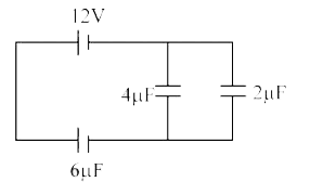
View SolutionThe charge on 4μFcapacitor in the given circuit is (inμC)

View SolutionA capacitor of capacitance C which is initially charged up to a potential differnce ε is connected with a battery of emf ε2 such that the positive terminal of the battery is connected with the positive plate of the capacitor. Find the heat loss in the circuit the process of charging.
View SolutionThe charge across the capacitor in two different RC circuit 1 and 2 are potted as shown in figure.
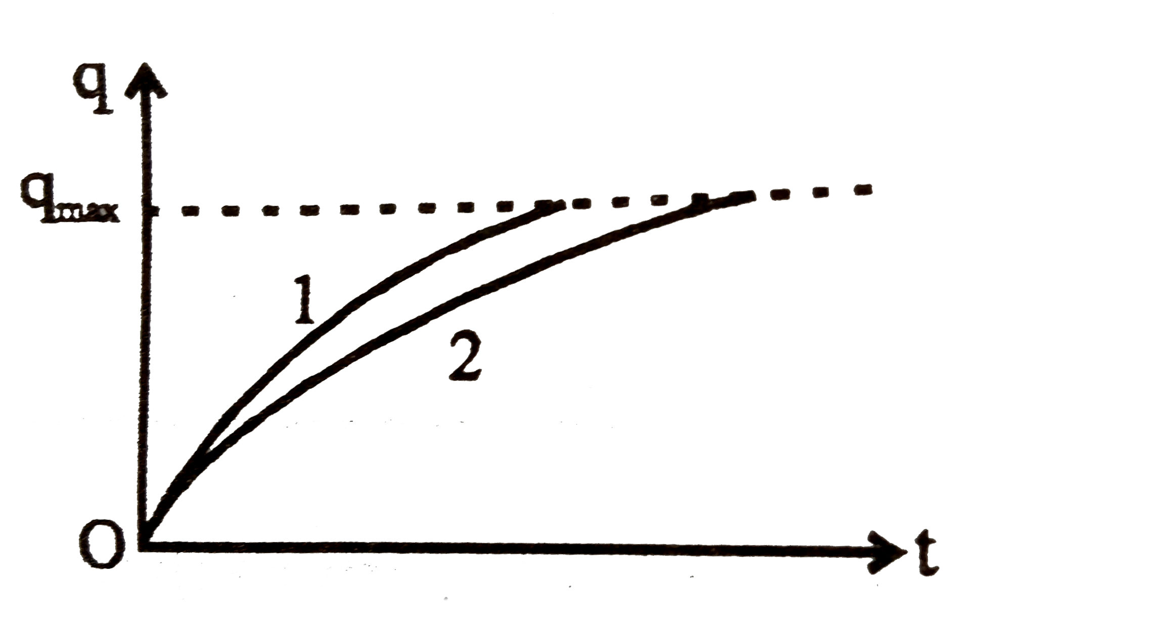
Choose the correct statement (s) related to the two circuit.
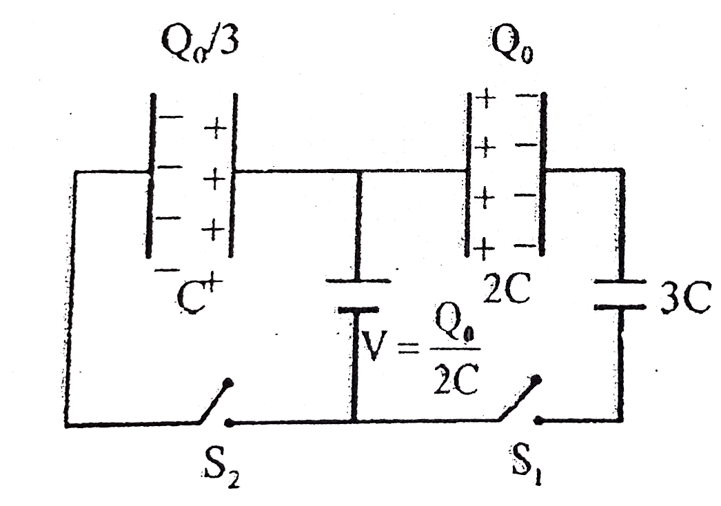
View SolutionIn the given circuit, the initial charges on the capacitors are shown in the figure. The charge flown through the switches S1andS2 respectively after closing the switches are
View SolutionDuring charging of capacitor in the circuit shown,

Circuit current versus time graph is
View Solution
