In the figure shown below ,the charge on the left plate of the 10μF capacitor is −30μC.The charge on the right plate of the 6μF capactior is :

+18μC
−18μC
−12μC
+12μC
The correct Answer is:A
By division of charge on capacitor in parallel,
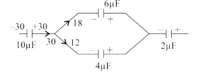 . q=+18μC.
Topper's Solved these Questions
- CAPACITORSBOOK - VMC MODULES ENGLISHCHAPTER - CAPACITORSEXERCISE - JEE Advance ( Archive ) LEVEL 2
1 Videos
- CAPACITORSBOOK - VMC MODULES ENGLISHCHAPTER - CAPACITORSEXERCISE - JEE Advance ( Archive ) LEVEL 3
1 Videos
- CAPACITORSBOOK - VMC MODULES ENGLISHCHAPTER - CAPACITORSEXERCISE - LEVEL 2
40 Videos
- BASIC MATHEMATICS & VECTORSBOOK - VMC MODULES ENGLISHCHAPTER - BASIC MATHEMATICS & VECTORSEXERCISE - Impeccable
50 Videos
- CURRENT ELECTRICITYBOOK - VMC MODULES ENGLISHCHAPTER - CURRENT ELECTRICITYEXERCISE - IN-CHAPTER EXERCISE-F
10 Videos
Similar Questions
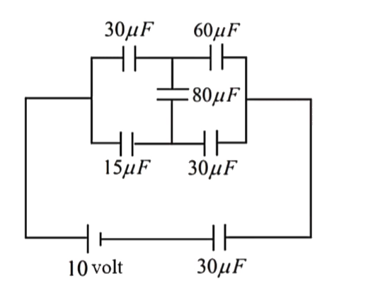
In the circuit shown below, the charge on the 60μF capacitor is
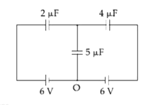
View SolutionIn the circuit shown , charge on the 5μF capacitor is :
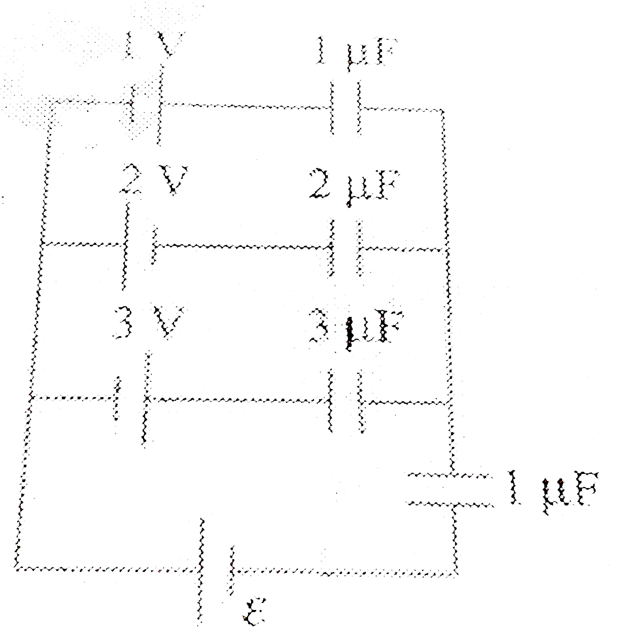
View SolutionIn the figure shown. Find the e.m.f. ɛ for which charge on 2μF capacitor is 4μC.
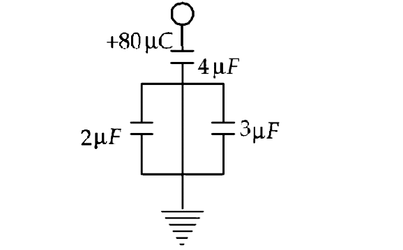
View SolutionIn the given circuit, a charge of +80μC is given to the upper plate of the 4μF capacitor. Then in the steady state, the charge on the upper plate of the 3μF capacitor is
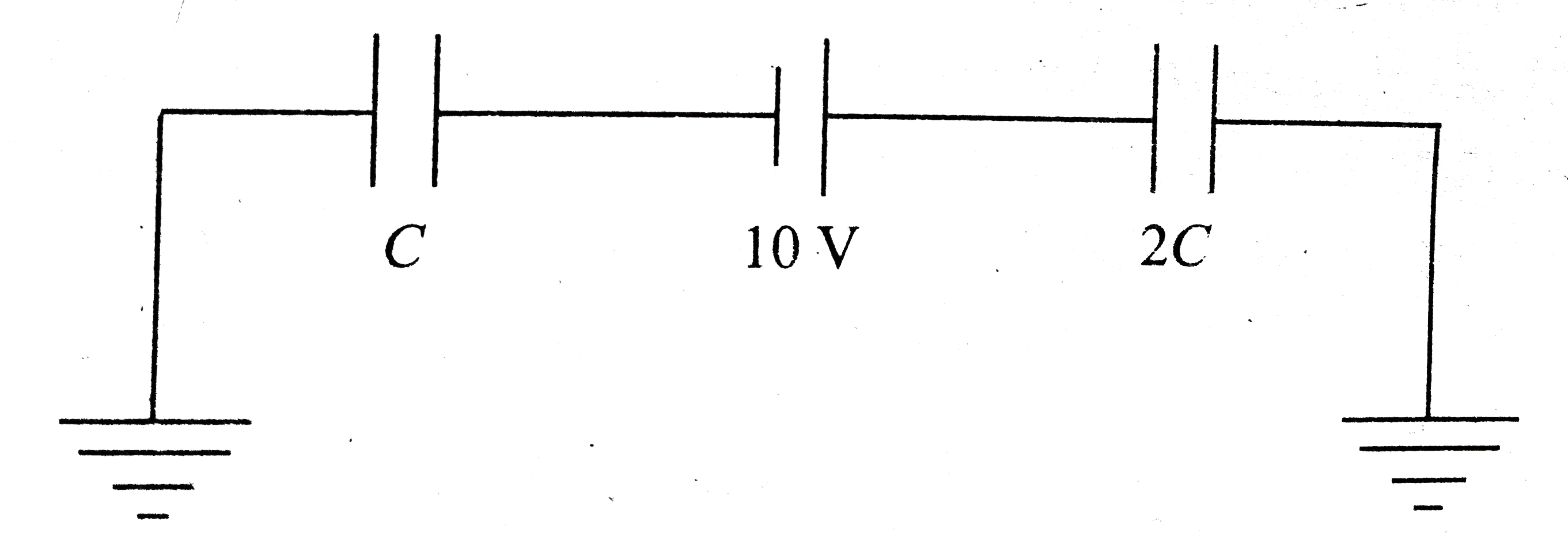
View SolutionThe potentials of the two plates of capacitor are +10V and −10V. The charge on one of the plate is 40C. The capacitance of the capacitor is
View SolutionIn the ciruit shown in, C=6μF. The charge stored in the capacitor of capacity C is
 .
.
View SolutionIn the ciruit shown in, C=6μF. The charge stored in the capacitor of capacity C is
 .
.
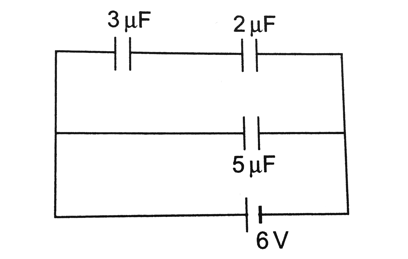
View SolutionIn the circuit shown in figure, the ratio of charge on 5μF and 2μF capacitor is
View SolutionIn the arrangement shown in in the switch S is , find
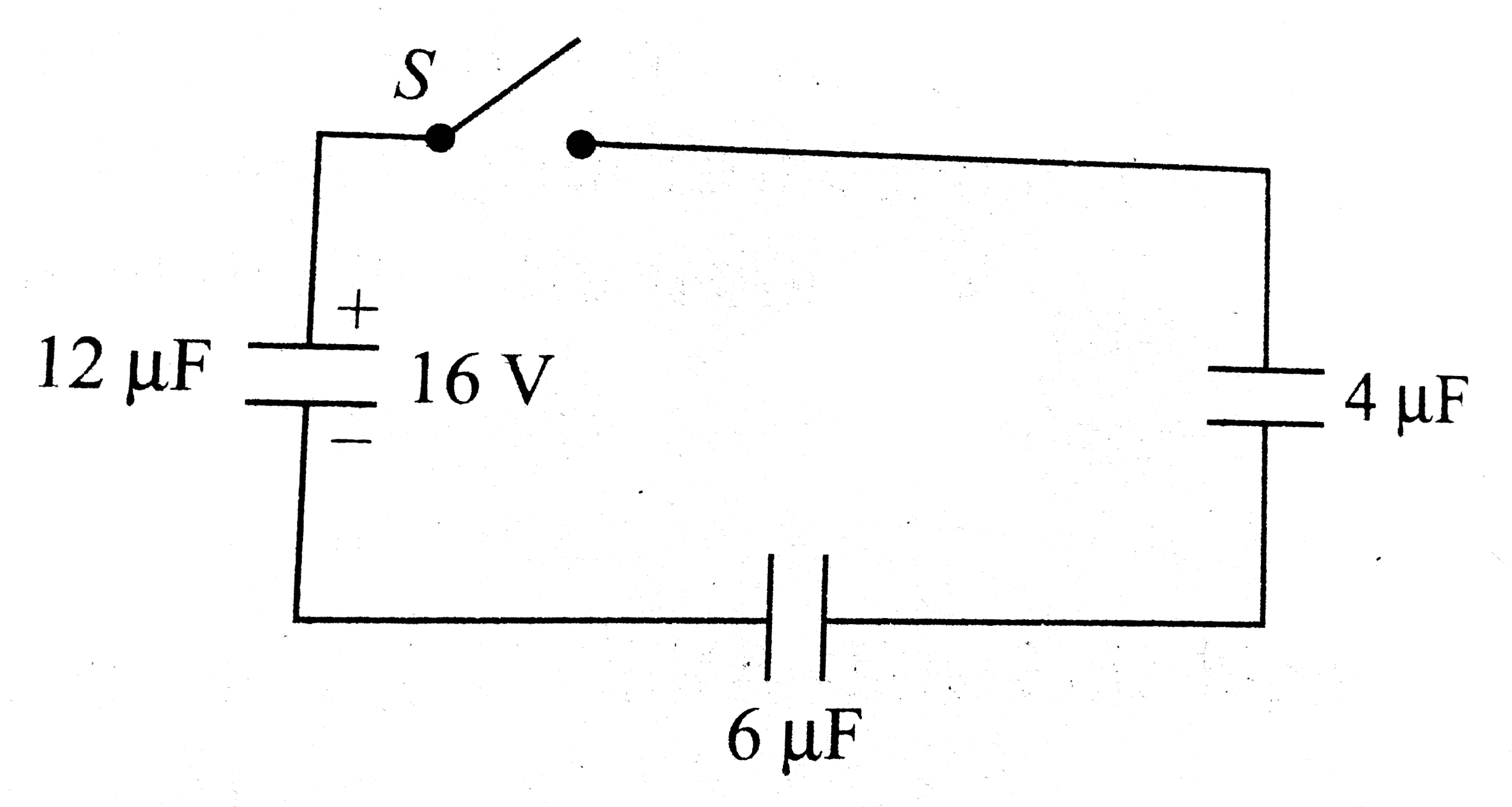
the final charge on the 6μF capacitor
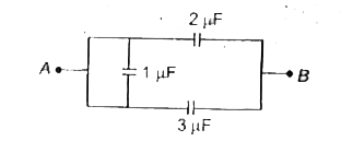
View SolutionIn the given circuit the charge on the plates of 1 μF capacitor, when 100 V battery is connected to the terminals A and B will be
View Solution
