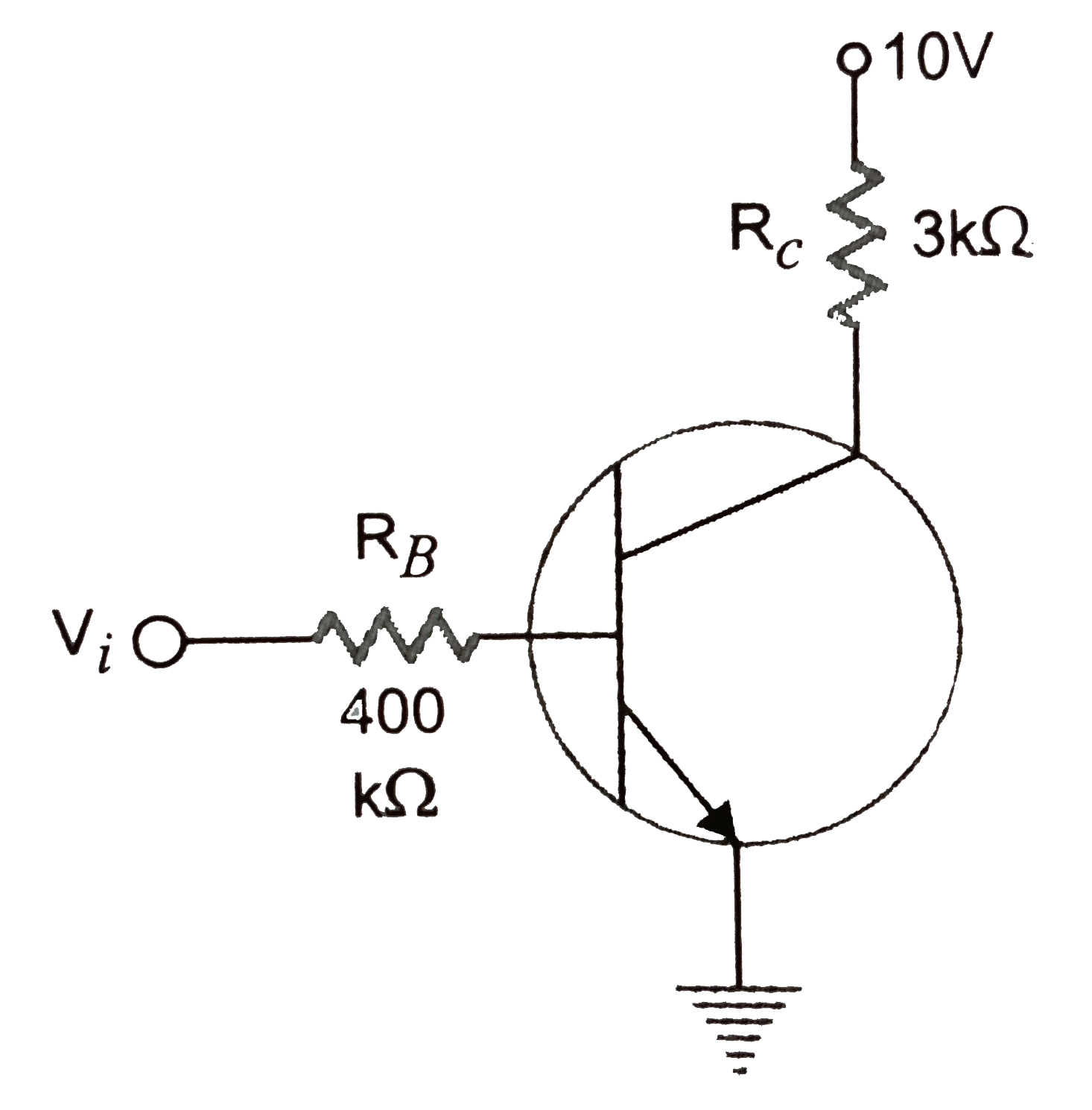
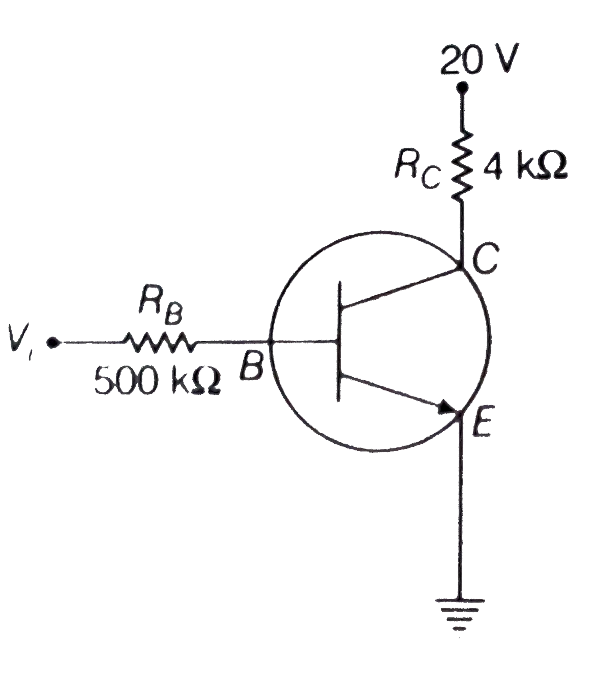
In the circuit shown in the figure, the input voltage Vi is 20V, VBE=0 and VCE=0. The values of IB, IC and β are given by
A
IB=20,μA,IC=5mA,β=250
B
IB=25μA,IC=5mA,β=200
C
IB=40μA,IC=10mA,β=250
D
IB=40μA,IC=5mA,β=125
Video Solution
Text Solution
The correct Answer is:D
VBE=0
VCE=0
Vb=0

IC=(20−0)4×10³
IC=5×10−3=5mA
Vi=VBE+IBRB
Vi=0+IBRB
20=IB×500×103
IB=20500×103=40μA
β=ICIb=25×10−340×10−6=125
|
Similar Questions
Knowledge Check
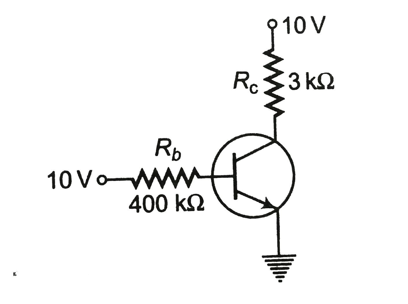
In the circuit shown in figure, when the input voltage of the base resistance is 10 V, Vbe is zero and Vce is also zero. Then
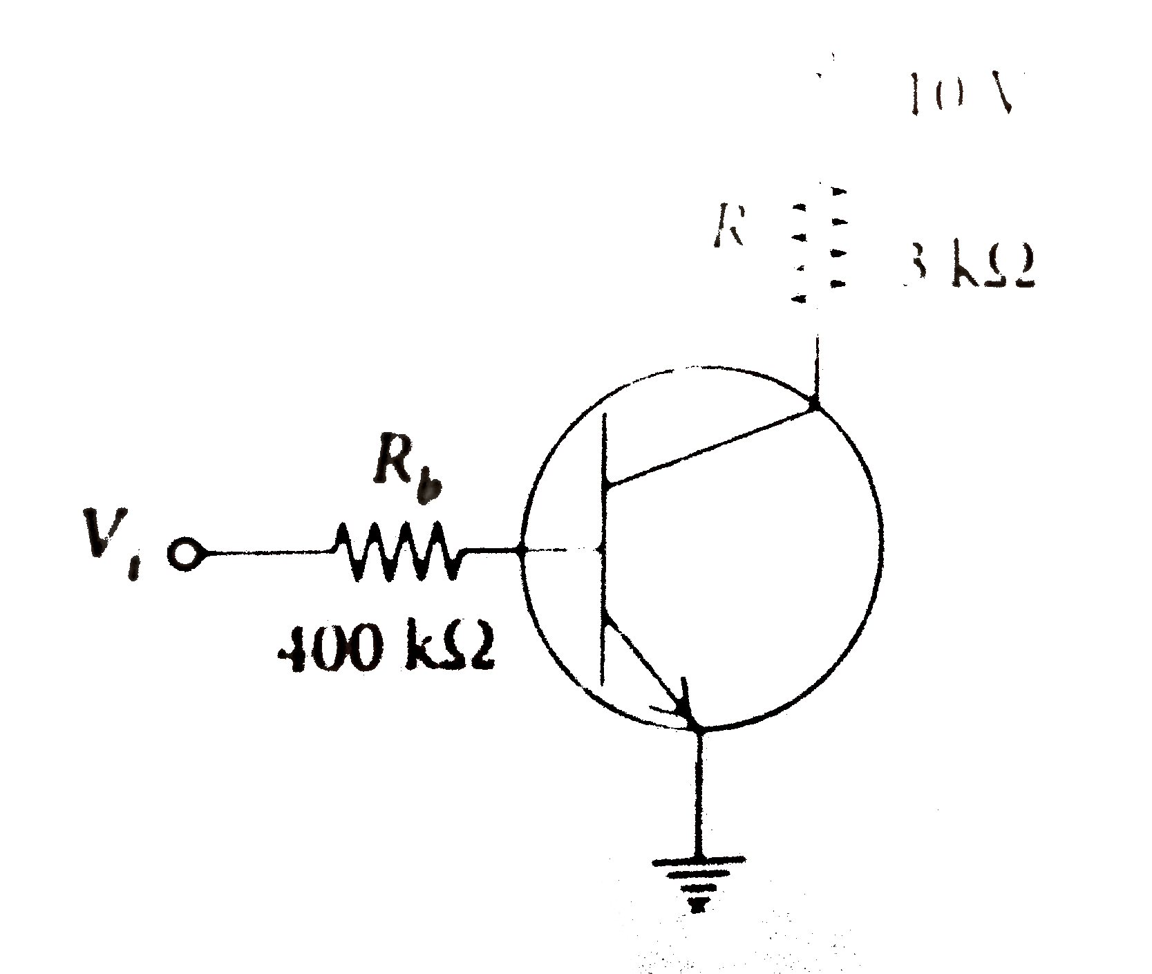 Aβ=110BIb=25μACIc=3.33mADboth (A) and (C )
The I-V characteristics shown in the figure represents
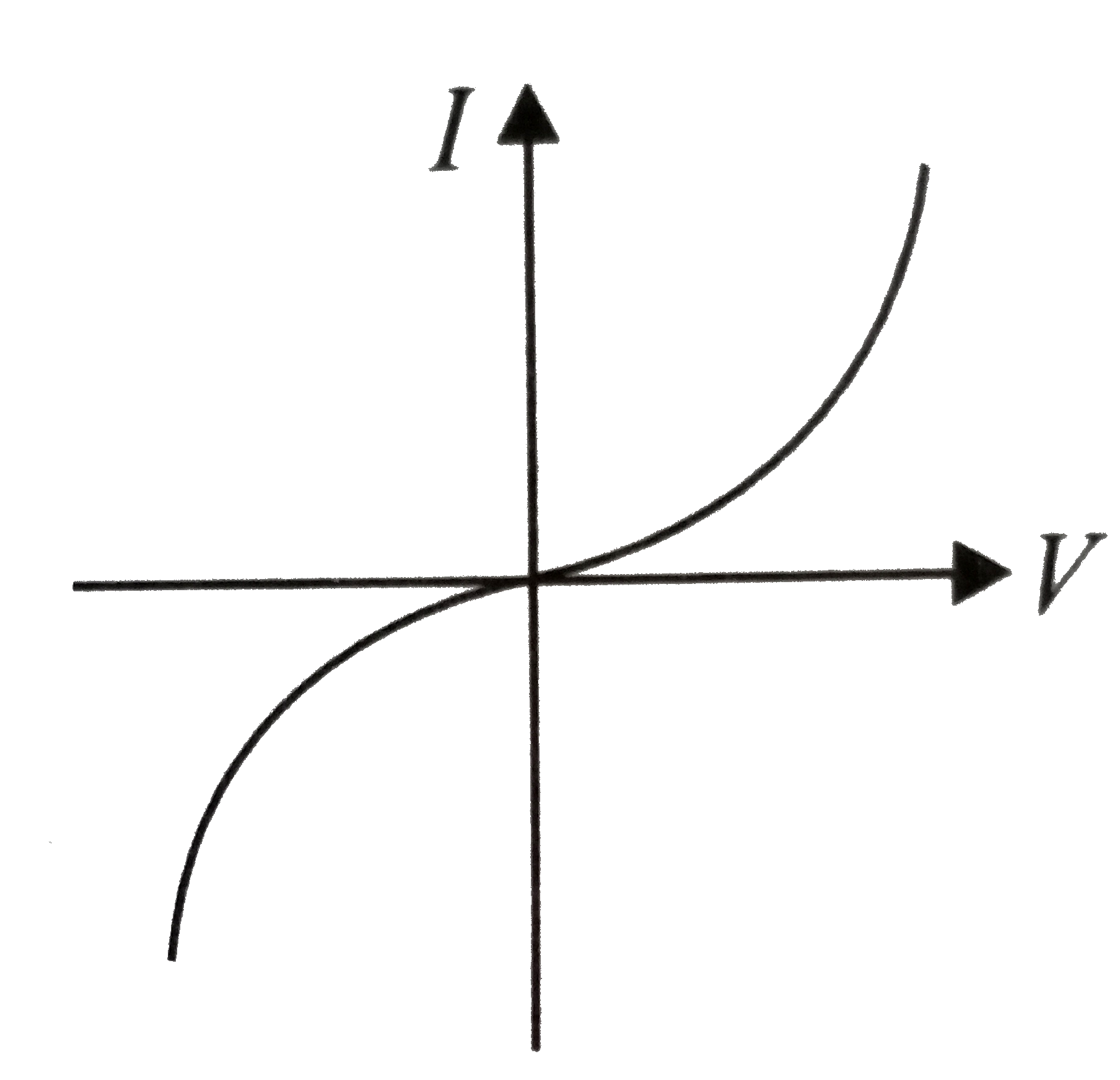 Aohmic conductorsBnon-ohmic conductorsCinsulatorsDsuperconductors
In the circuit shown in figure, if the A diode forward voltage drop is 0.3 V, the voltage difference between A and B is
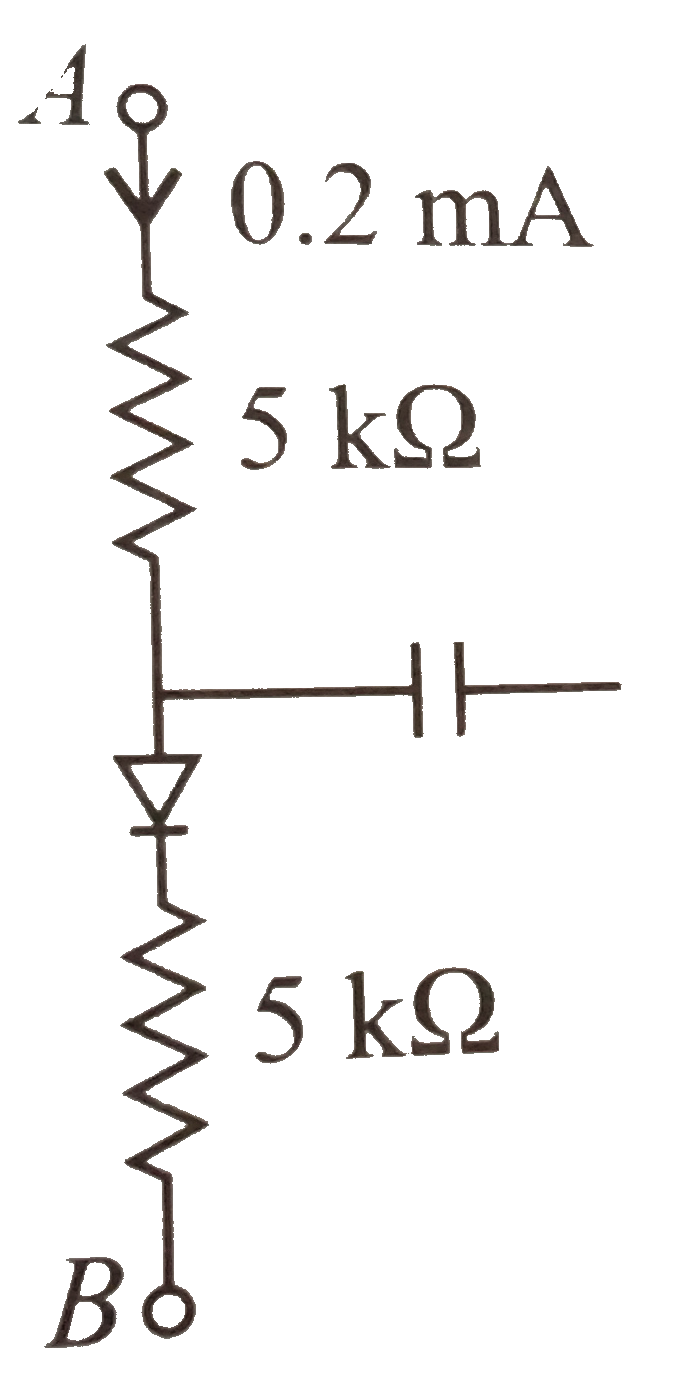 A1.3 VB2.3 VC0D0.5 V
In the circuit shown in figure when the input voltage of the base resistance is 10 V . Find the values of Ib,Icandβ .
View SolutionIn the circuit shown in figure, if the diode forward voltage drop is 0.3 V, then the voltage difference between A to B is,

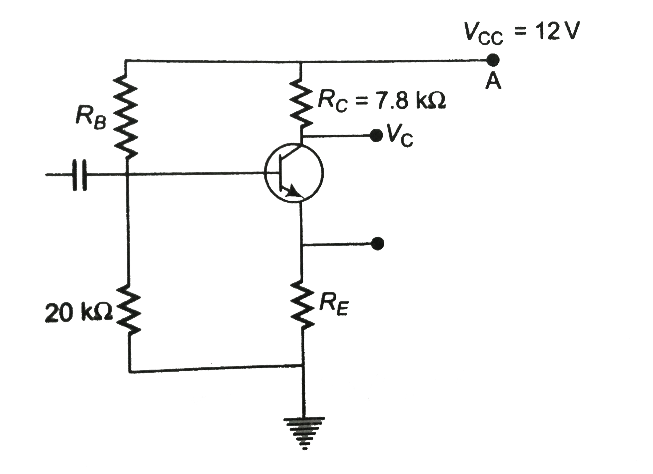
View SolutionFor the transistor circuit shown in figure , evaluate VE,RBandRE. Given IC=1mA,
VCE=3V,VBE=0.5V,VC=12Vandβ=100
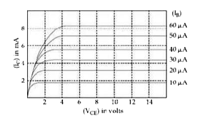
View SolutionThe output characteristics of a transistor is shown in the figure. When VCE is 10 V and IC=4.0mA, then value of βac is _________
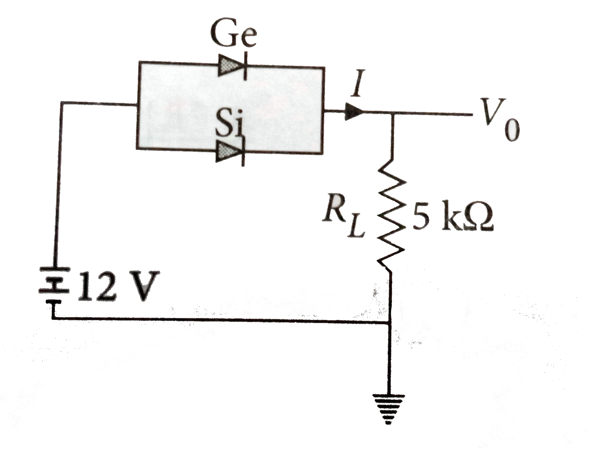
View SolutionIn the circuit shown in figure, the silicon and germanium diodes start conducting at 0.7 V and 0.3 V respectively. What are the values of V0 and I?
View Solution

