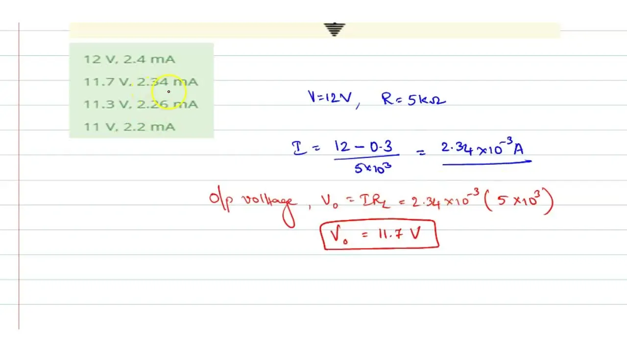
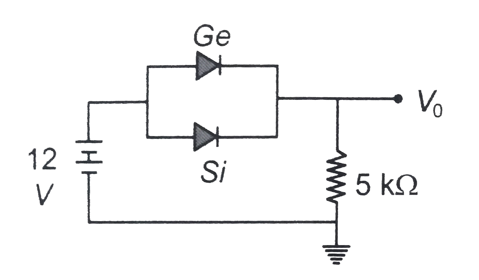
In the circuit shown in figure, the silicon and germanium diodes start conducting at 0.7 V and 0.3 V respectively. What are the values of V0 and I?
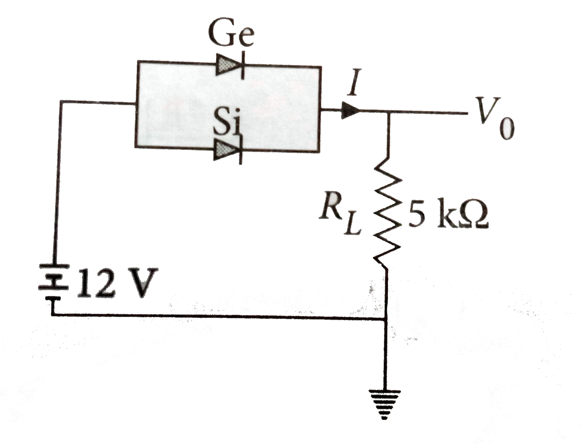
12 V, 2.4 mA
11.7 V, 2.34 mA
11.3 V, 2.26 mA
11 V, 2.2 mA
The correct Answer is:B
The germanium diode will start conducting before the silicon diode does so. The voltage across Ge = 0.3 V. The output voltage V0 is the voltage across R= 12 -0.3 = 11.7 V
The current I =11.7V5kΩ=11.75×103
=2.34×10⁻³A=2.34mA
Related Playlists
- BOOK - NCERT FINGERTPS ENGLISHCHAPTER - SEMICONDUCTOR ELECTRONICS : MATERIALS , DEVICES AND SIMPLE CIRCUITS EXERCISE - NCERT8videos
SEMICONDUCTOR ELECTRONICS : MATERIALS , DEVICES AND SIMPLE CIRCUITS
- BOOK - NCERT FINGERTPS ENGLISHCHAPTER - SEMICONDUCTOR ELECTRONICS : MATERIALS , DEVICES AND SIMPLE CIRCUITS EXERCISE - ASSERTION & REASON15videos
SEMICONDUCTOR ELECTRONICS : MATERIALS , DEVICES AND SIMPLE CIRCUITS
- BOOK - NCERT FINGERTPS ENGLISHCHAPTER - SEMICONDUCTOR ELECTRONICS : MATERIALS , DEVICES AND SIMPLE CIRCUITS EXERCISE - Assertion And Reason15videos
SEMICONDUCTOR ELECTRONICS : MATERIALS , DEVICES AND SIMPLE CIRCUITS
- BOOK - NCERT FINGERTPS ENGLISHCHAPTER - RAY OPTICS AND OPTICAL INSTRUMENTSEXERCISE - NCERT Exemplar11videos
RAY OPTICS AND OPTICAL INSTRUMENTS
- BOOK - NCERT FINGERTPS ENGLISHCHAPTER - WAVE OPTICSEXERCISE - Assertion And Reason15videos
WAVE OPTICS
Similar Questions
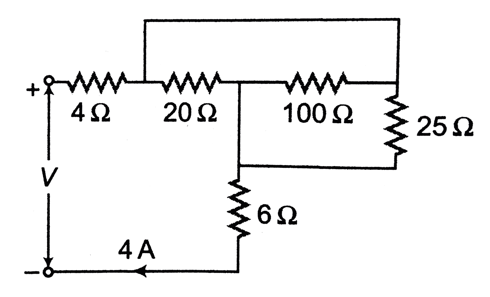
In the circuit shown in figure , V must be
 View Solution
In the circuit shown in figure , V must be
 View Solution
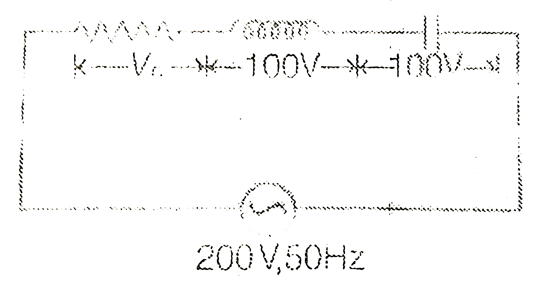
In the circuit shown in figure value of VR is
 View Solution
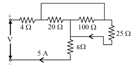
In the circuit shown in the figure , V must be -
 View Solution
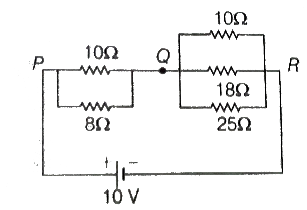
Find VP−VQ in the circuit shown in figure.
 View Solution
Calculate the value of V0 and I If the Si diode and the Ge diode start conducting ar 0.7 V and 0.3 volt respectively. In the given circuit. If the Ge diode connection be reversed. What will the new value of V0 and I ?
_S01_052_Q01.png) .View Solution
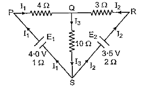
.View SolutionIn the circuit shown in figure below, E1 and E2 are batteries having emfs 4.0 V and 3.5 V respectively and internal resistance 1Ω and 2Ω respectively. Using Kirchhoff.s laws, calculate currents : I1,I2 and I3.
 View Solution
In the network shown in fig. , points A, B, and C are at potentials of 70 V, 0, and 10V, respectively.
 View Solution
Ge and Si diodes conduct at 0.3V and 0.7V respectively. In the following figure if Ge diode connection are reversed, the value of V0 changes by
 View Solution
In the circuit shown in figure, if the diode forward voltage drop is 0.3 V, then the voltage difference between A to B is,
 View Solution

