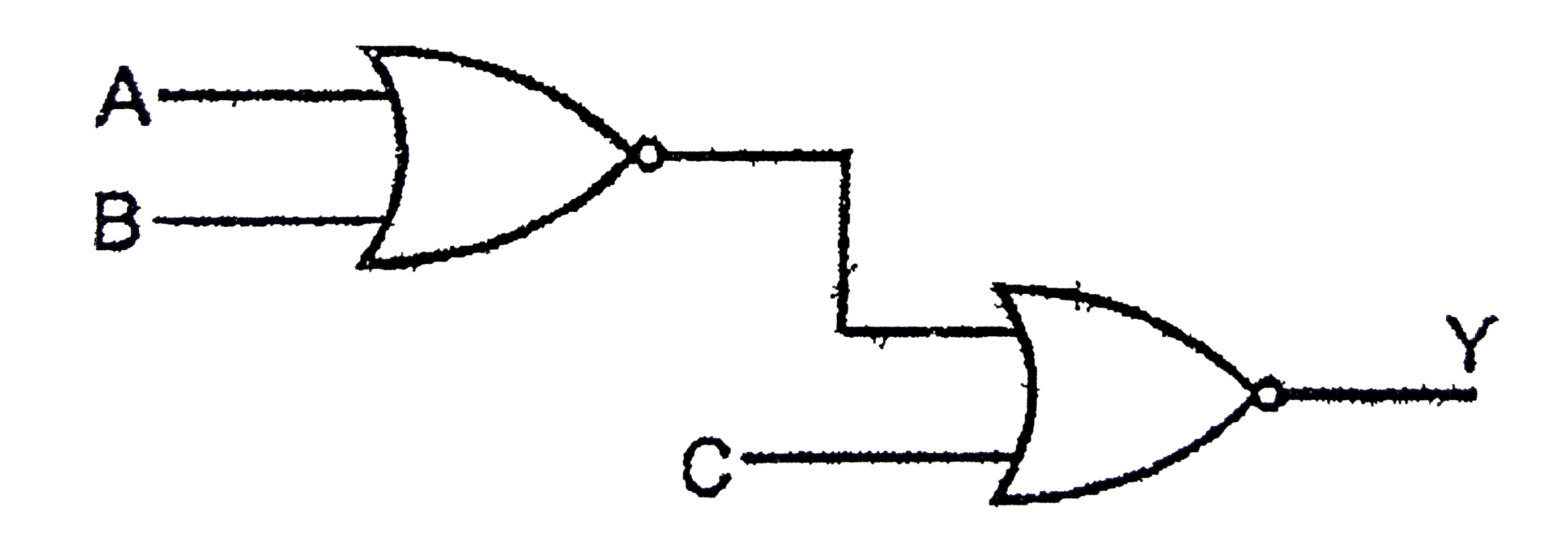
The Boolean expression of the output y in terms of the input A and B for the circuit shown in figure.

A
¯¯¯AB+A¯¯¯B
B
AB
C
AB+¯¯¯A¯¯¯B
D
A¯¯¯B+1
Video Solution
Text Solution
The correct Answer is:C
The output from the upper AND gate =(¯¯¯A.B)
The output from the lower AND gate =(A.¯¯¯B)
The output y of the NOR gate is
y=¯¯¯¯¯¯¯¯¯¯¯¯¯¯¯¯¯¯¯¯¯¯¯¯¯¯¯¯(¯¯¯A.B)+(A.¯¯¯B)
=¯¯¯¯¯¯¯¯¯¯¯¯(¯¯¯A.B)+¯¯¯¯¯¯¯¯¯¯¯¯(A.¯¯¯B)=(A+¯¯¯B)(¯¯¯A+B)
=A¯¯¯A+AB+¯¯¯B¯¯¯A+¯¯¯BB=AB+¯¯¯A¯¯¯B
|
Topper's Solved these Questions
- SEMICONDUCTOR ELECTRONICS : MATERIALS , DEVICES AND SIMPLE CIRCUITS BOOK - NCERT FINGERTPS ENGLISHCHAPTER - SEMICONDUCTOR ELECTRONICS : MATERIALS , DEVICES AND SIMPLE CIRCUITS EXERCISE - NCERT
8 Videos
- SEMICONDUCTOR ELECTRONICS : MATERIALS , DEVICES AND SIMPLE CIRCUITS BOOK - NCERT FINGERTPS ENGLISHCHAPTER - SEMICONDUCTOR ELECTRONICS : MATERIALS , DEVICES AND SIMPLE CIRCUITS EXERCISE - ASSERTION & REASON
15 Videos
- SEMICONDUCTOR ELECTRONICS : MATERIALS , DEVICES AND SIMPLE CIRCUITS BOOK - NCERT FINGERTPS ENGLISHCHAPTER - SEMICONDUCTOR ELECTRONICS : MATERIALS , DEVICES AND SIMPLE CIRCUITS EXERCISE - Assertion And Reason
15 Videos
- RAY OPTICS AND OPTICAL INSTRUMENTSBOOK - NCERT FINGERTPS ENGLISHCHAPTER - RAY OPTICS AND OPTICAL INSTRUMENTSEXERCISE - NCERT Exemplar
11 Videos
- WAVE OPTICSBOOK - NCERT FINGERTPS ENGLISHCHAPTER - WAVE OPTICSEXERCISE - Assertion And Reason
15 Videos
Similar Questions
Knowledge Check
The Boolean expression for the given circuit is
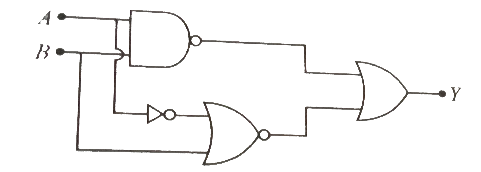 A¯¯¯¯¯¯¯¯A.BBA+BC¯¯¯A+BDA+¯¯¯B
The equivalent resistance between A and B for . the circuit shown in this figure is
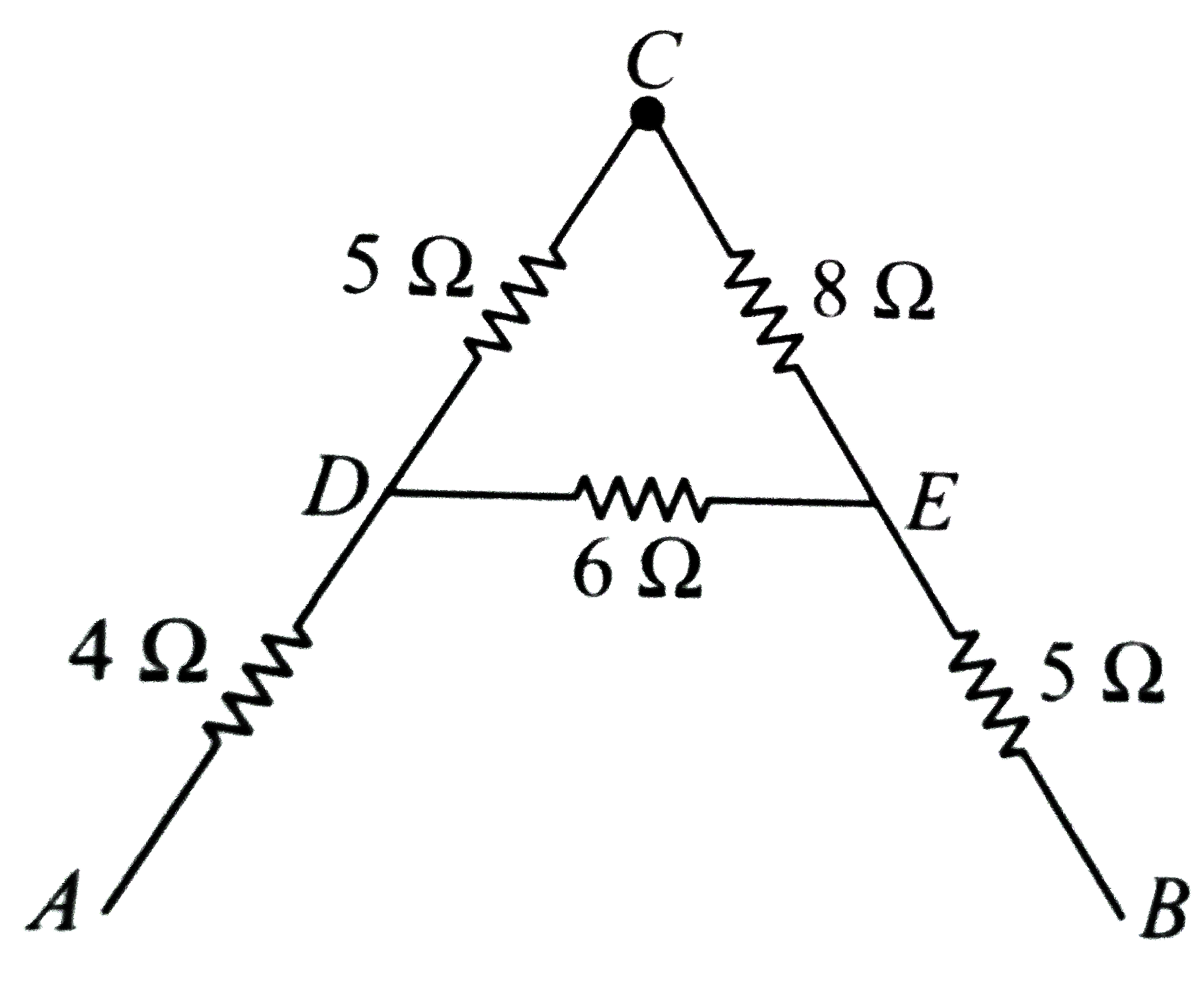 A13.1ΩB15.1ΩC17.1ΩD19.1Ω
Output Y of the gate shown in figure
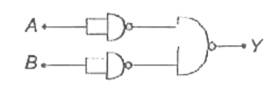
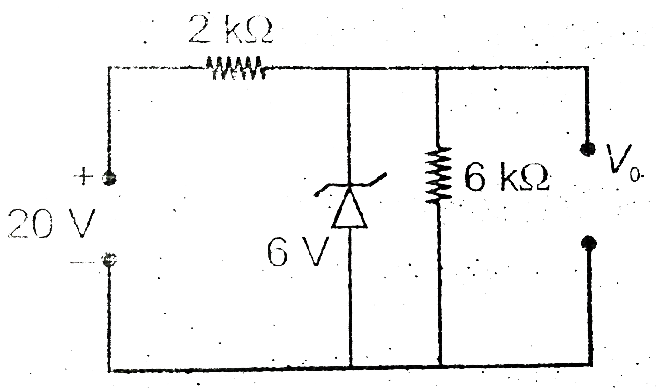
View SolutionWhat is the value of output voltage V0 in the circuit shown in the figure ?
View SolutionTo get an output 1 from the circuit shown in figure the input must be :

View SolutionTo get an output of 1 form the circuit shown in figure the input must be :-
_E01_514_Q01.png)
View SolutionThe Boolean expression P+¯¯¯PQ, where P and Q are the inputs of the logic circuit, represents
View SolutionThe output of the given circuit in figure:
View Solution

