In the circuit shown in Fig.
if we assume that when the input voltage at the base resistance is 5V,VBE is zero and VCE is also zero. What is I,I and beta?
When the input is zero, then I is zero. What would be the output wave form if the input wave form is as shown in Fig.
For current in emitter-base circuit VBE=ECE−IBRB=0
or IB=ECERB=5V200kΩ=25μA
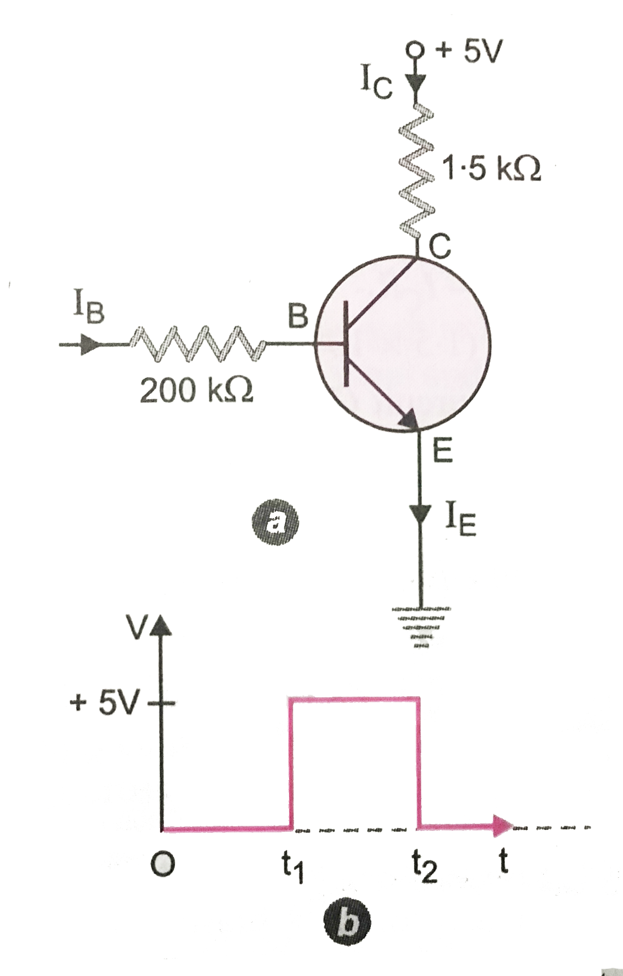
For current in collector emitter circuit
VCE=ECE−ICRL=0
or IC=ECERL=5V1.5kΩ=3.33mA
Now β=ICIB=3.33mA25μA=3.33×10⁻³A25×10−6A
=133.2
The output waveform will be antophase as it is common-emitter amplifier.
Topper's Solved these Questions
- ELECTRONIC DEVICESBook:PRADEEPChapter:ELECTRONIC DEVICESExercise:SAMPLE PROBLEM
Explore 2 Videos
- ELECTRONIC DEVICESBook:PRADEEPChapter:ELECTRONIC DEVICESExercise:CONCEPTUAL PROBLEMS
Explore 1 Video
- ELECTROMAGNETIC WAVESBook:PRADEEPChapter:ELECTROMAGNETIC WAVESExercise:II Focus multiple choice question
Explore 5 Videos
- ELECTROSTATICSBook:PRADEEPChapter:ELECTROSTATICSExercise:ASSERTION-REASON TYPE QUESTIONS
Explore 2 Videos
Similar Questions
In the accompanying circuit Fig. 5.10, if it is assumed that when that input voltage at the base resistance is 5 V, VBE is zero and VCE is also zero, what are IB,ICandβ ? When the input is zero, IB is zero. What will be the output waveform if the input waveform is as shown in the figure ? What is the practial use of this current ?
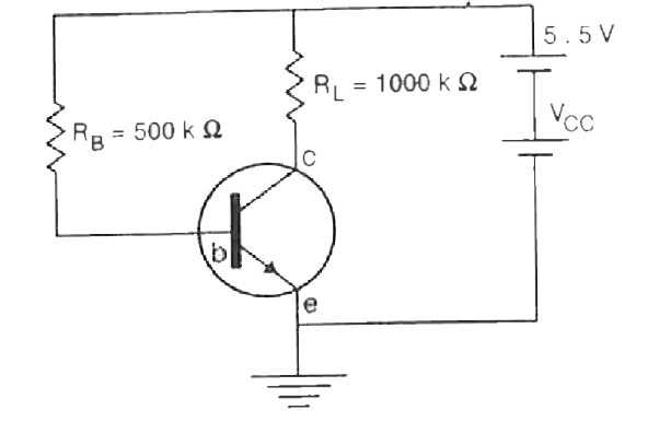
View SolutionIn the circuit shown in Fig. when the input voltage of the base resistance is 10V,Vbe is zero and Vce is also zero. Find the values of I,I and β.
View Solution
Knowledge Check
In the circuit shown in figure, when the input voltage of the base resistance is 10 V, Vbe is zero and Vce is also zero. Then
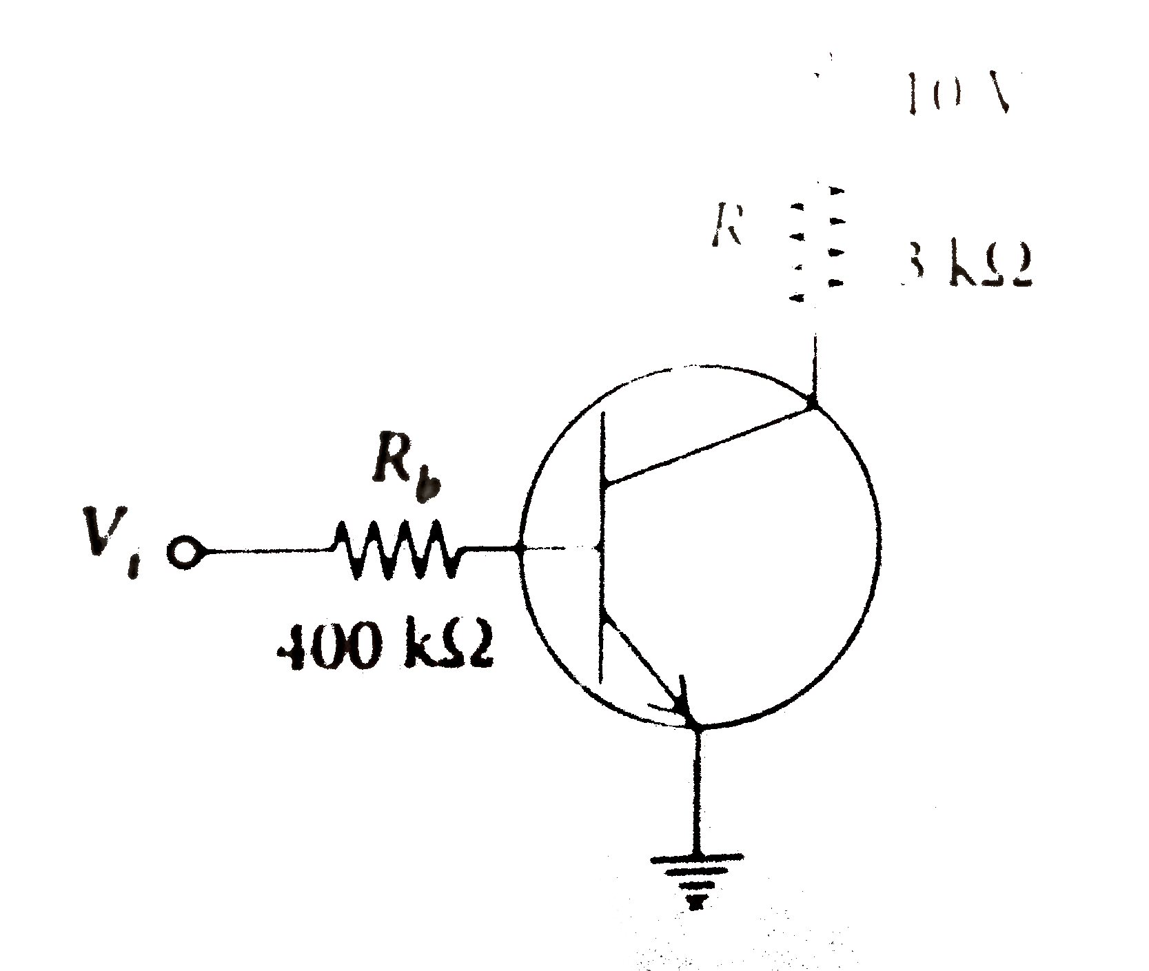 Aβ=110BIb=25μACIc=3.33mADboth (A) and (C )
In the circuit Fig. the output y becomes zero for the inputs
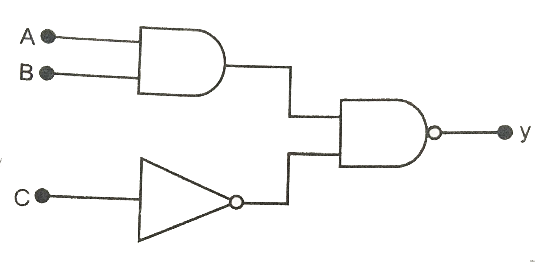 AA=1,B=0,C=0BA=0,B=1,C=1CA=0,B=0,C=0DA=1,B=1,C=0
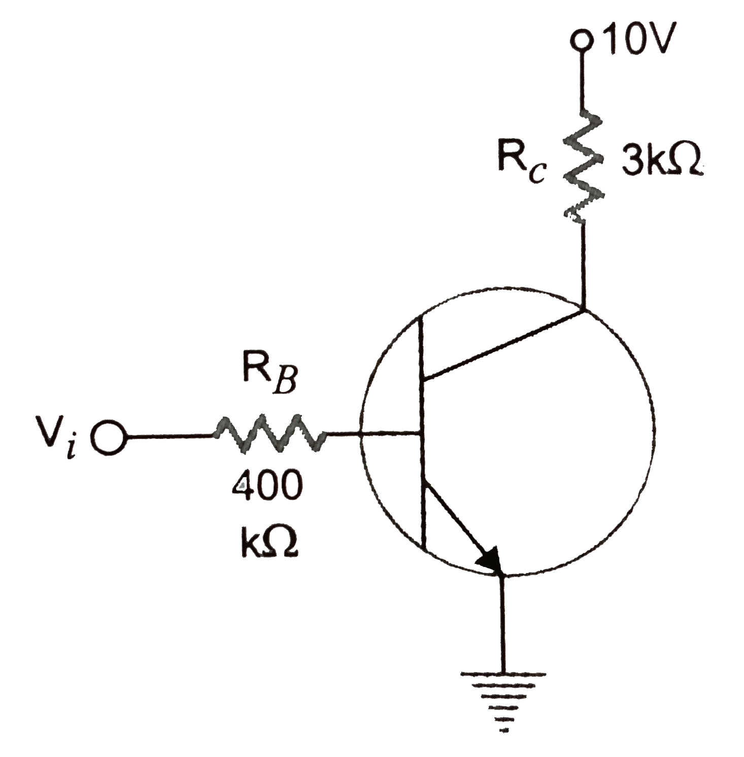
In the circuit shown in the figure, the input voltage Vi is 20V,VBE=0 and VCE=0. The values of IB,IC and β are given by:
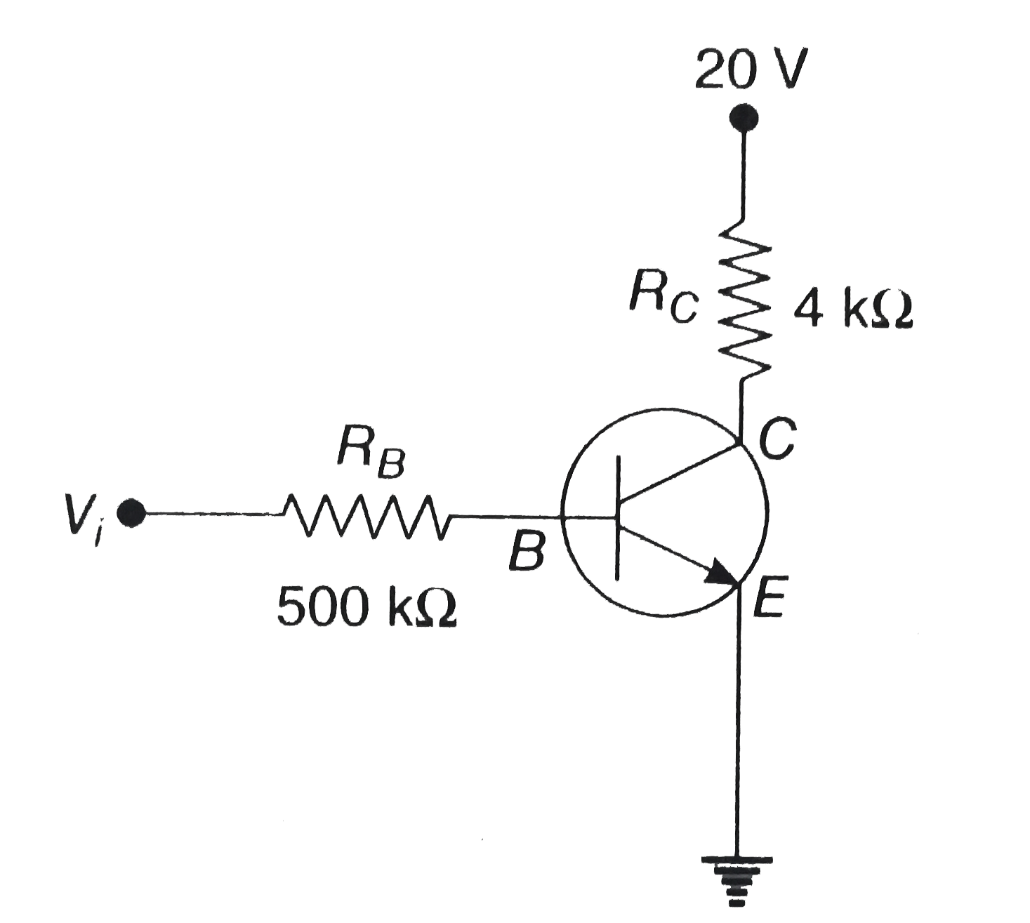 AIB=40μA,IC=10mA,β=250BIB=25μA,IC=5mA,β=200CIB=20μA,IC=5mA,β=250DIB=40μA,IC=5mA,β=125
In the circuit shown in figure when the input voltage of the base resistance is 10 V . Find the values of Ib,Icandβ .
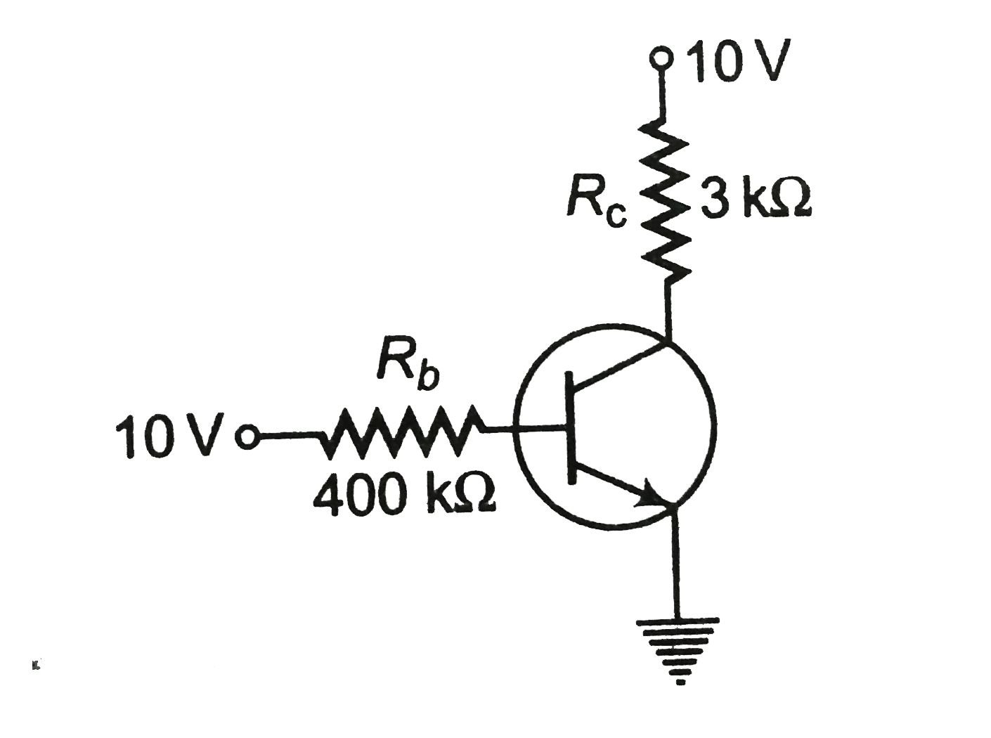
View SolutionIn the circuit shown, the current I will be zero when R is
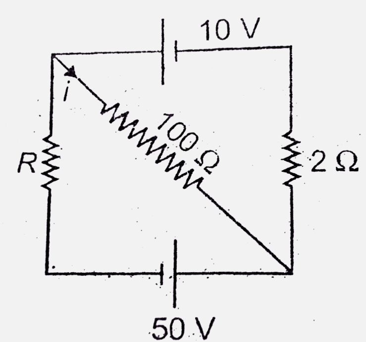
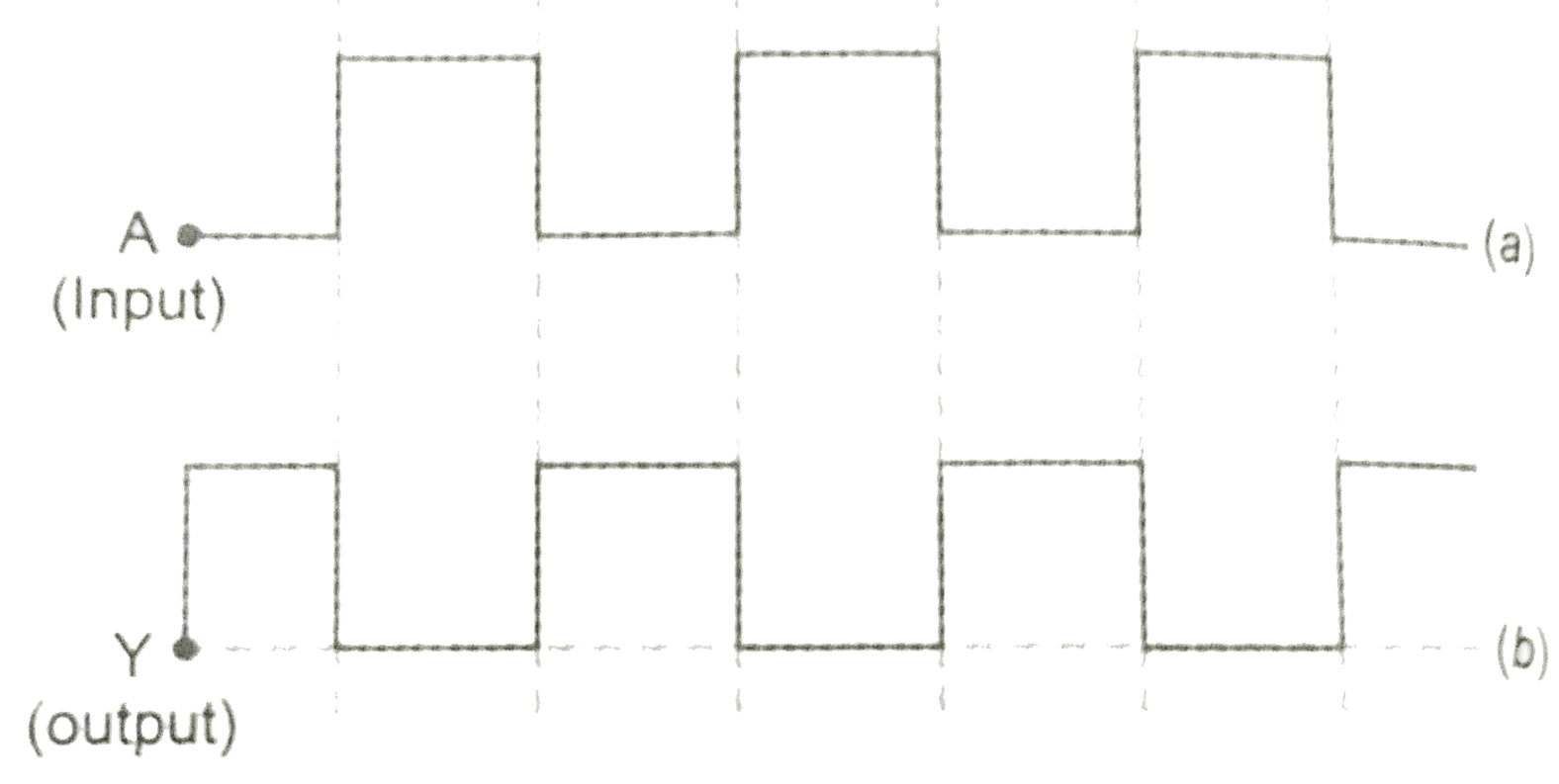
View SolutionThe input wave form for NOT gate is shown in Fig.Draw the output wave form of this gate.
View SolutionIn the circuit shown in the figure, the input voltage Vi is 20V, VBE=0 and VCE=0. The values of IB, IC and β are given by
View SolutionIn the circuit shown in the figure, the input voltage Vi is 20V,VBE=0 and VCE=0. The values of IB,IC and β are given by:

View Solution

