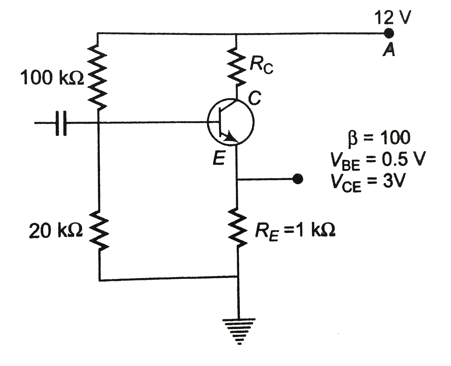
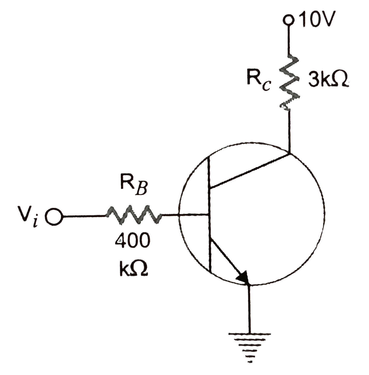
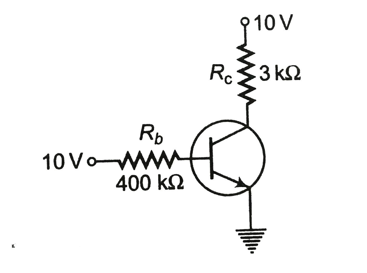
In the circuit shown in figure when the input voltage of the base resistance is 10 V . Find the values of Ib,Icandβ .
Video Solution
Text Solution
The correct Answer is:A, B, C
Given circuit is equivalent to
(##DCPV05C35E01025_S01.png width=80%><br>Inbaseemierl∞p,<br> V_B = I_B R_B <br> rArr I_B = V_B / R_B = 10 / (400 xx 10^(3))<br> = 25 xx 10^(-6) A <br> = 25 mu A <br>Inemier−col≤c→rl∞p,<br> V_C = I_C R_C <br> rArr I_C = 10 / (3 xx 10^(3)) <br> and βDC=ICIB=3.33mA25μA
=133
|
Topper's Solved these Questions
- SEMICONDUCTORSBOOK - DC PANDEY ENGLISHCHAPTER - SEMICONDUCTORSEXERCISE - More Than One Correct
6 Videos
- REFRACTION OF LIGHTBOOK - DC PANDEY ENGLISHCHAPTER - REFRACTION OF LIGHTEXERCISE - Level 2 Subjective
21 Videos
- SOLVED PAPER 2017BOOK - DC PANDEY ENGLISHCHAPTER - SOLVED PAPER 2017EXERCISE - Solved papers 2017(JIPMER)
32 Videos
Similar Questions
Knowledge Check
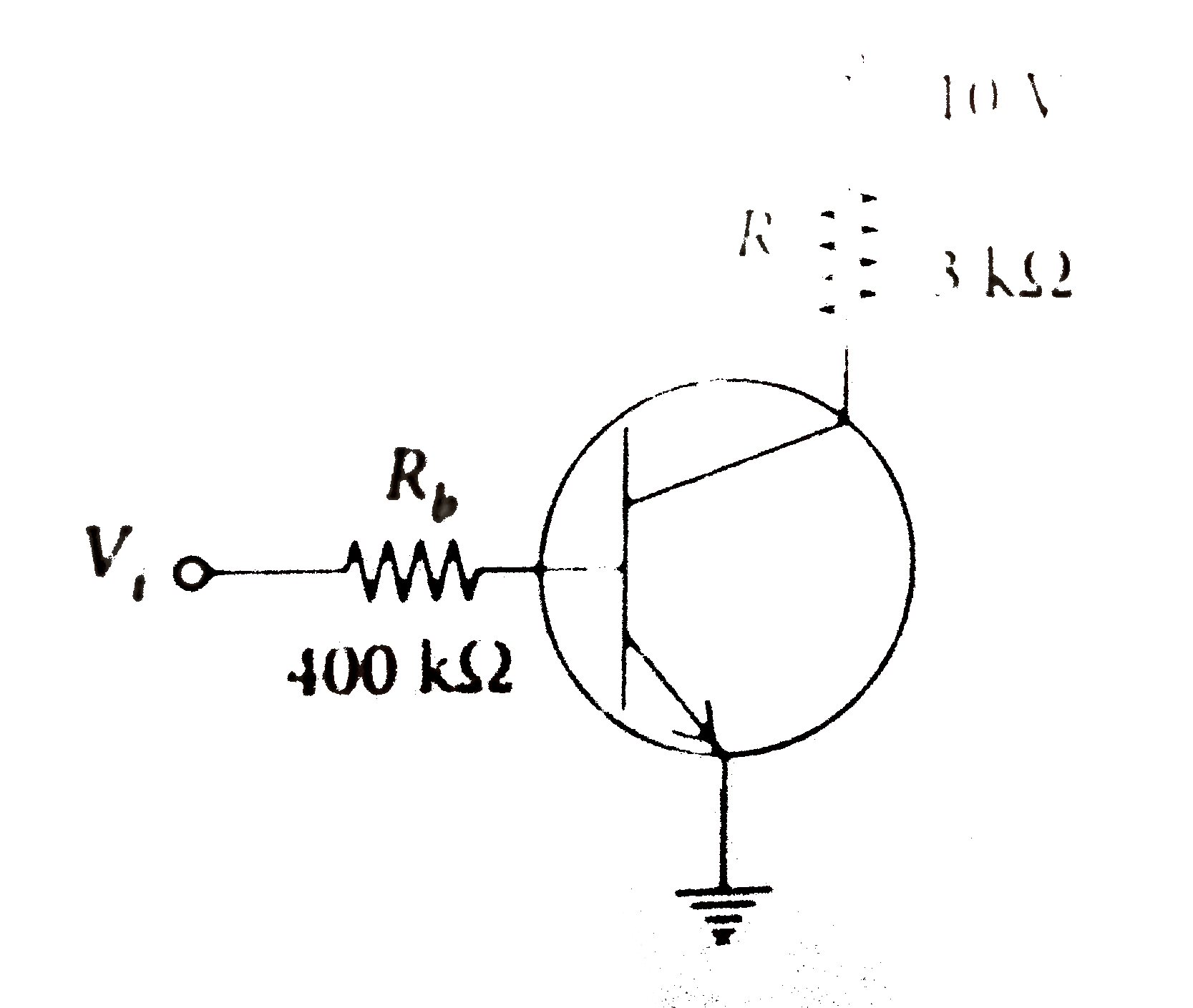
In the circuit shown in figure, when the input voltage of the base resistance is 10 V, Vbe is zero and Vce is also zero. Then
 Aβ=110BIb=25μACIc=3.33mADboth (A) and (C )
In the circuit shown in figure value of VR is
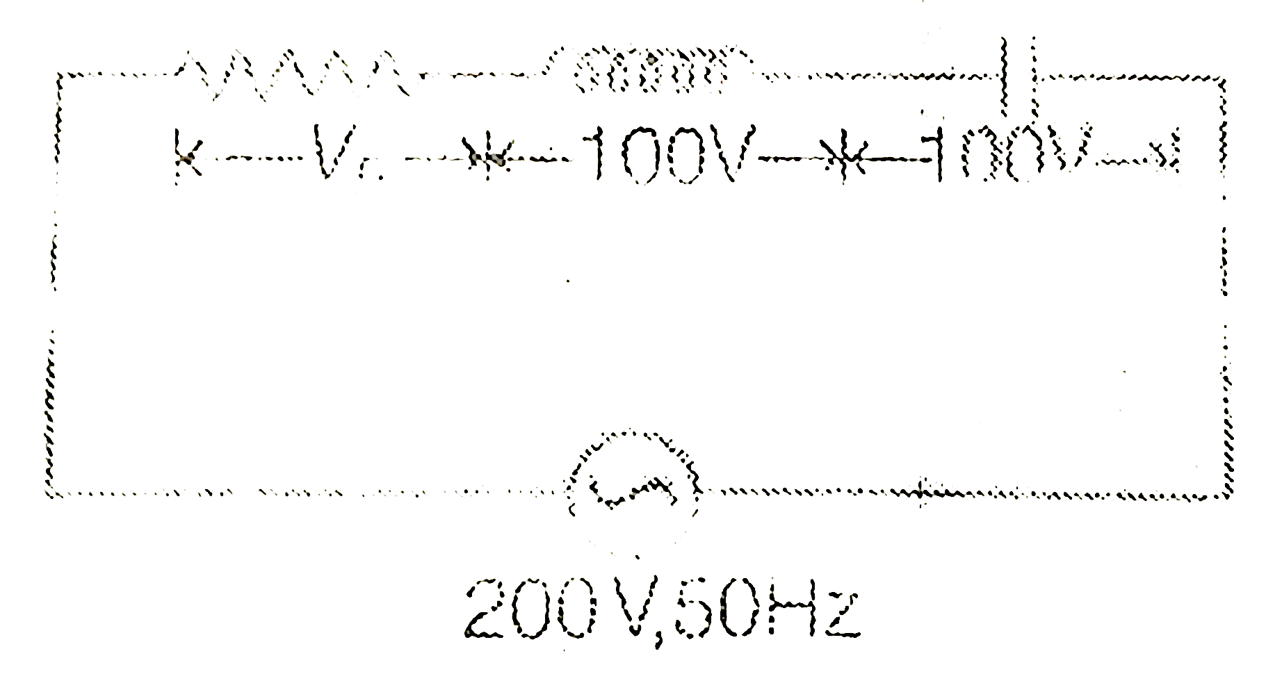
View SolutionIn the circuit shown in the figure
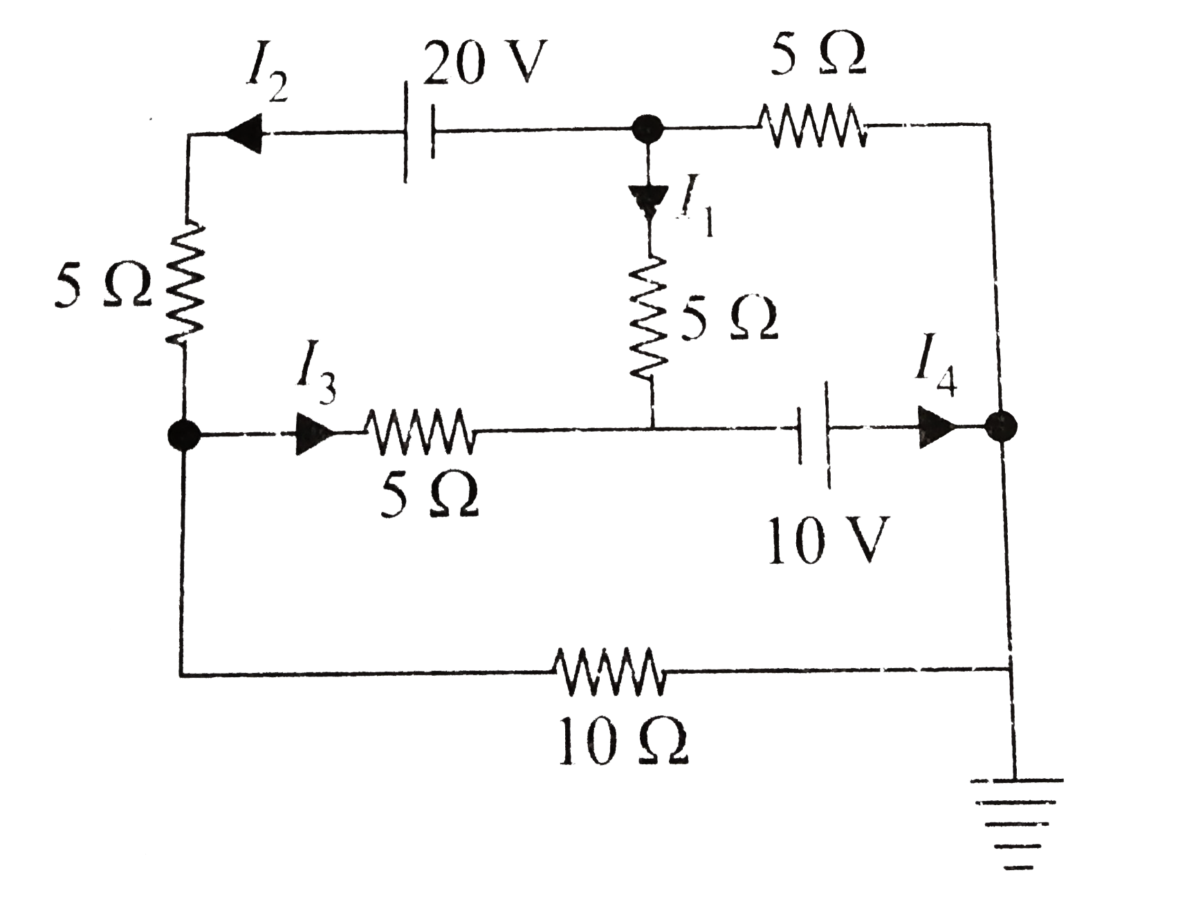 .
.
The value of current I4 is
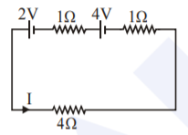
View SolutionFor the circuit shown in the figure current I will be
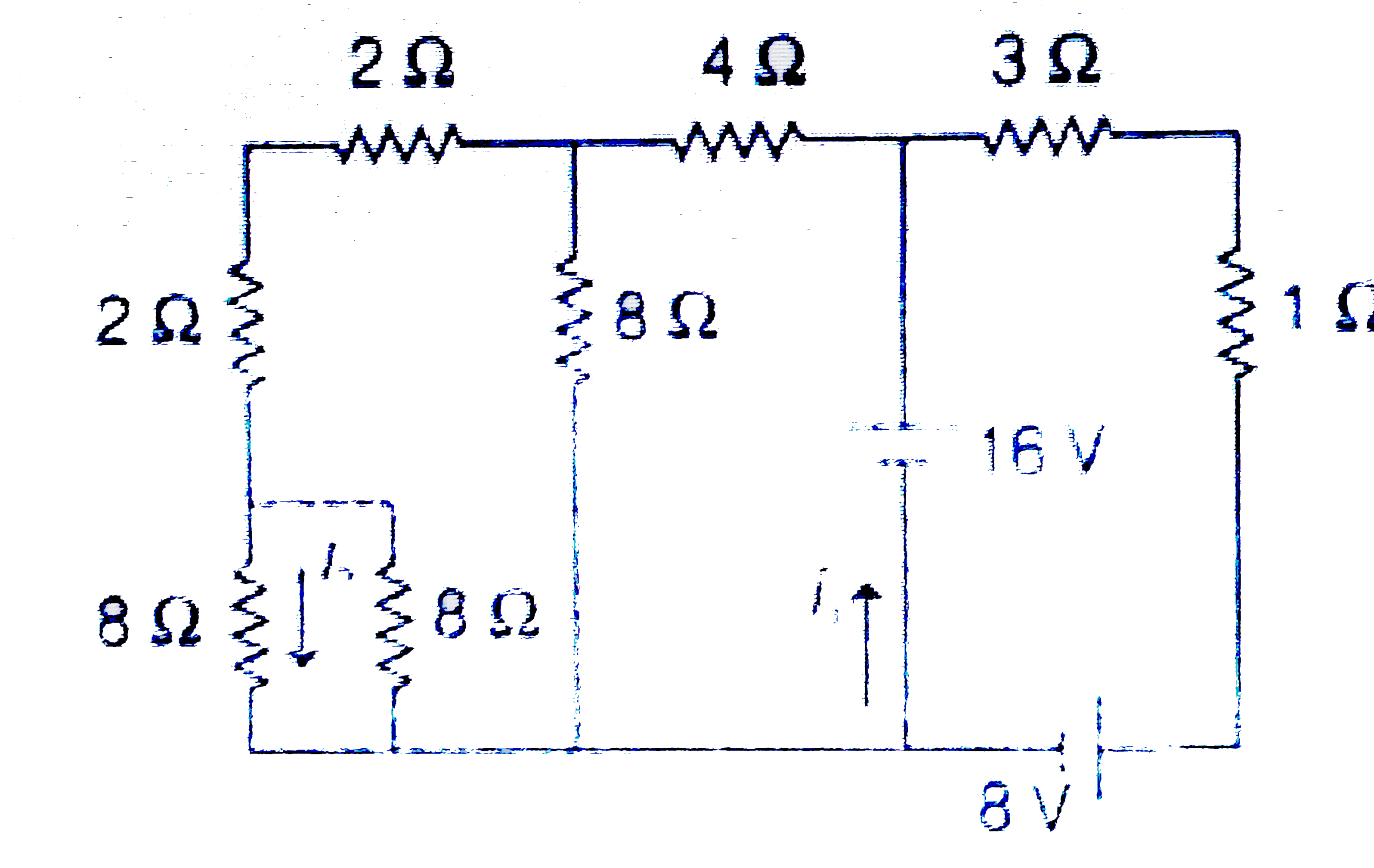
View SolutionIn the circuit shown in figure ,find the ratio of currents i1/i2.
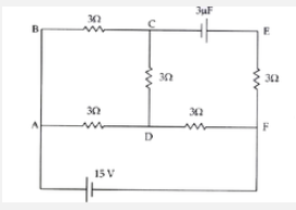
View SolutionIn the circuit shown in the figure, find the total resistance of the circuit and current in CD arm.
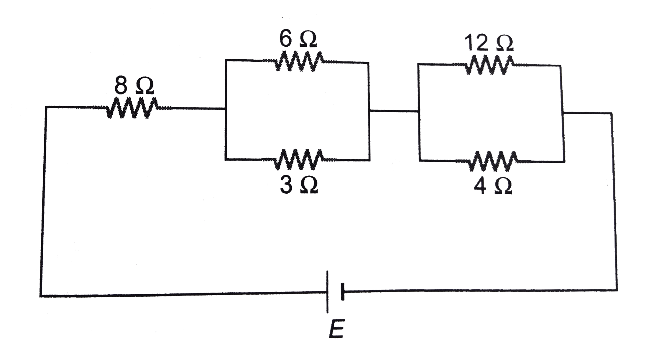
View SolutionIn the circuit shown in figure potential differences across 6Ω resistance is 4 volt. Find V and i values across each resistance. Also find emf E of the applied battery.
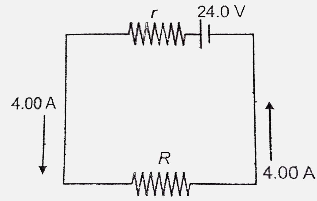
View SolutionConsider the circuit shown in Figure . Ther terminal voltage of the 24.0 V battery is 21.2V. What are
(a) The internal resistance r of the battery and
(b) The resistance R of the circuit resistor ?
View Solution

