Can the potential barrier across a p-n junction be measured by simply connecting a voltmeter across the junction ?
To determine whether the potential barrier across a p-n junction can be measured by simply connecting a voltmeter across the junction, we can analyze the situation step by step:
Step 1: Understanding the p-n Junction
A p-n junction is formed by joining p-type and n-type semiconductors. At the junction, electrons from the n-side and holes from the p-side recombine, creating a depletion region that has a built-in electric field and a potential barrier.
Step 2: Concept of Potential Barrier
The potential barrier is the energy barrier that must be overcome for charge carriers (electrons and holes) to move across the junction. This barrier prevents the free flow of charge carriers under equilibrium conditions.
Step 3: Connecting a Voltmeter
When we connect a voltmeter across the p-n junction, we are trying to measure the potential difference. However, the voltmeter has a very high internal resistance compared to the resistance of the p-n junction.
Step 4: Effect of High Resistance
Due to the high resistance of the voltmeter, it draws very little current. As a result, there are not enough charge carriers moving across the junction to create a measurable voltage reading on the voltmeter.
Step 5: Conclusion
Since the voltmeter cannot draw sufficient current to allow charge carriers to reach it, it cannot measure the potential barrier of the p-n junction. Therefore, the answer to the question is no; the potential barrier cannot be measured by simply connecting a voltmeter across the junction.
Summary
In summary, the potential barrier across a p-n junction cannot be measured using a voltmeter due to the high resistance of the voltmeter compared to the junction, which prevents sufficient charge flow to produce a measurable voltage.
---
A p-n junction is formed by joining p-type and n-type semiconductors. At the junction, electrons from the n-side and holes from the p-side recombine, creating a depletion region that has a built-in electric field and a potential barrier.
The potential barrier is the energy barrier that must be overcome for charge carriers (electrons and holes) to move across the junction. This barrier prevents the free flow of charge carriers under equilibrium conditions.
When we connect a voltmeter across the p-n junction, we are trying to measure the potential difference. However, the voltmeter has a very high internal resistance compared to the resistance of the p-n junction.
Due to the high resistance of the voltmeter, it draws very little current. As a result, there are not enough charge carriers moving across the junction to create a measurable voltage reading on the voltmeter.
Since the voltmeter cannot draw sufficient current to allow charge carriers to reach it, it cannot measure the potential barrier of the p-n junction. Therefore, the answer to the question is no; the potential barrier cannot be measured by simply connecting a voltmeter across the junction.
In summary, the potential barrier across a p-n junction cannot be measured using a voltmeter due to the high resistance of the voltmeter compared to the junction, which prevents sufficient charge flow to produce a measurable voltage.
Topper's Solved these Questions
- SEMICONDUCTORSBook:DC PANDEY ENGLISHChapter:SEMICONDUCTORSExercise:More Than One Correct
Explore 6 Videos
- REFRACTION OF LIGHTBook:DC PANDEY ENGLISHChapter:REFRACTION OF LIGHTExercise:Level 2 Subjective
Explore 21 Videos
- SOLVED PAPER 2017Book:DC PANDEY ENGLISHChapter:SOLVED PAPER 2017Exercise:Solved papers 2017(JIPMER)
Explore 32 Videos
Similar Questions
Knowledge Check
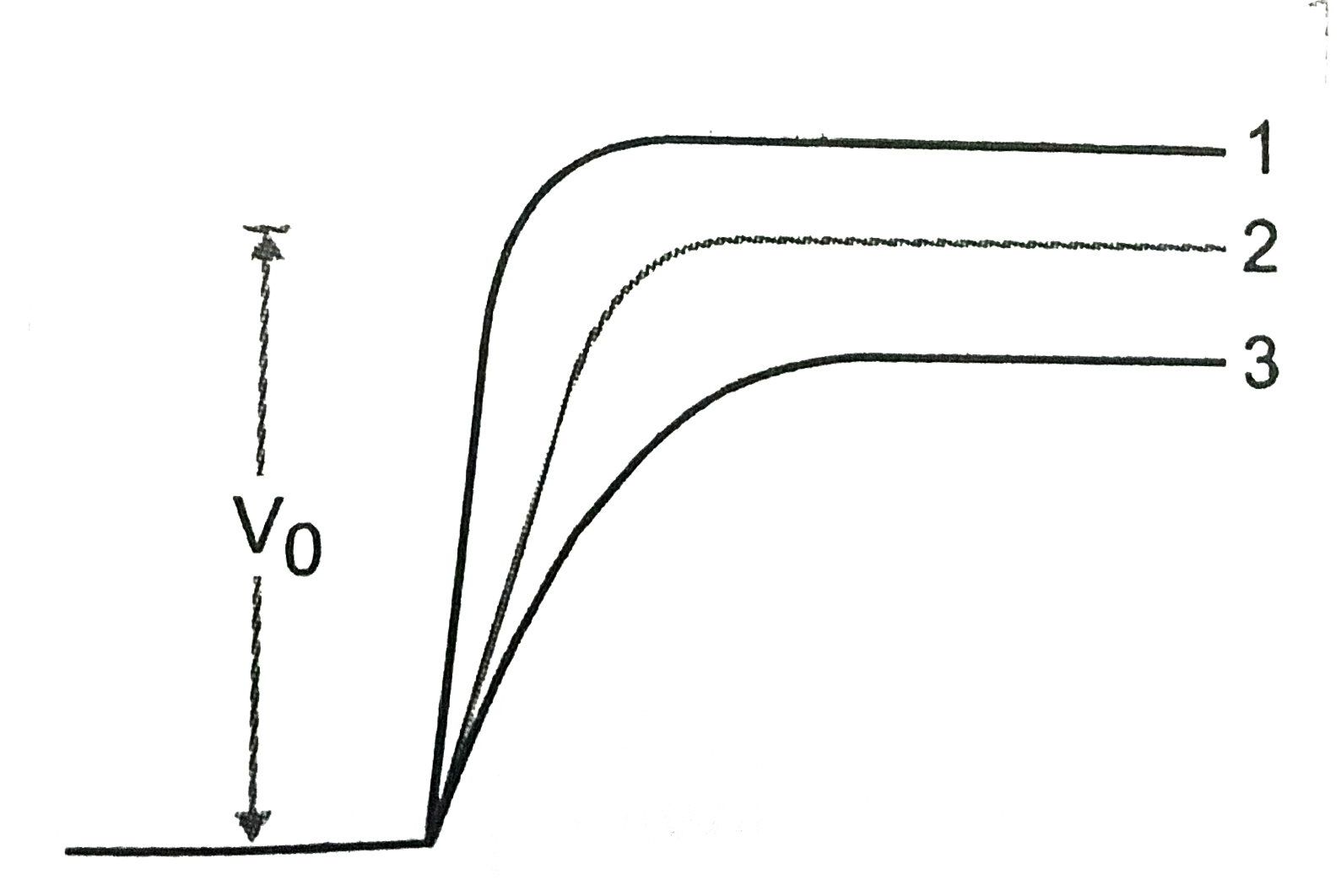
In Fig . V0 is the potential barrier across a p-n junction, when no battery is connected across the junction
 A1 and 3 both correspond to forward bias of junctionB3 corresponds to forward bias of junction and 1 corresponds to reverse bias of junctionC1 corresponds to forward bias and 3 corresponds to reverse bias of junction.D3 and 1 both correspond to reverse bias of junction.
A voltmeter having a resistance of 1800Ω employed to measure the potential difference across a 200Ω resistor which is connected to the terminals of a dc power supply having an emf of 50 V and an internal resistance of 20Ω. What is the percentage decrease in the potential difference across the 200Ω resistor as a result of connecting the voltmeter across it?
A1%B5%C10%D25%
Barrier potential of a p−n junction diode does not depend on
View SolutionBarrier potential of a p−n junction diode does not depend on
View SolutionA high resistance voltmeter measures the potential difference across a battery to be 9-0 V. On connecting a 24 2 resistor across the terminals of the battery, the voltmeter reads 7.2 V. Calculate the internal resistance of the battery.
View SolutionIn a p-n junction with open ends,
View SolutionIn a p-n junction with open ends,
View SolutionThe P-N junction is-
View Solution

