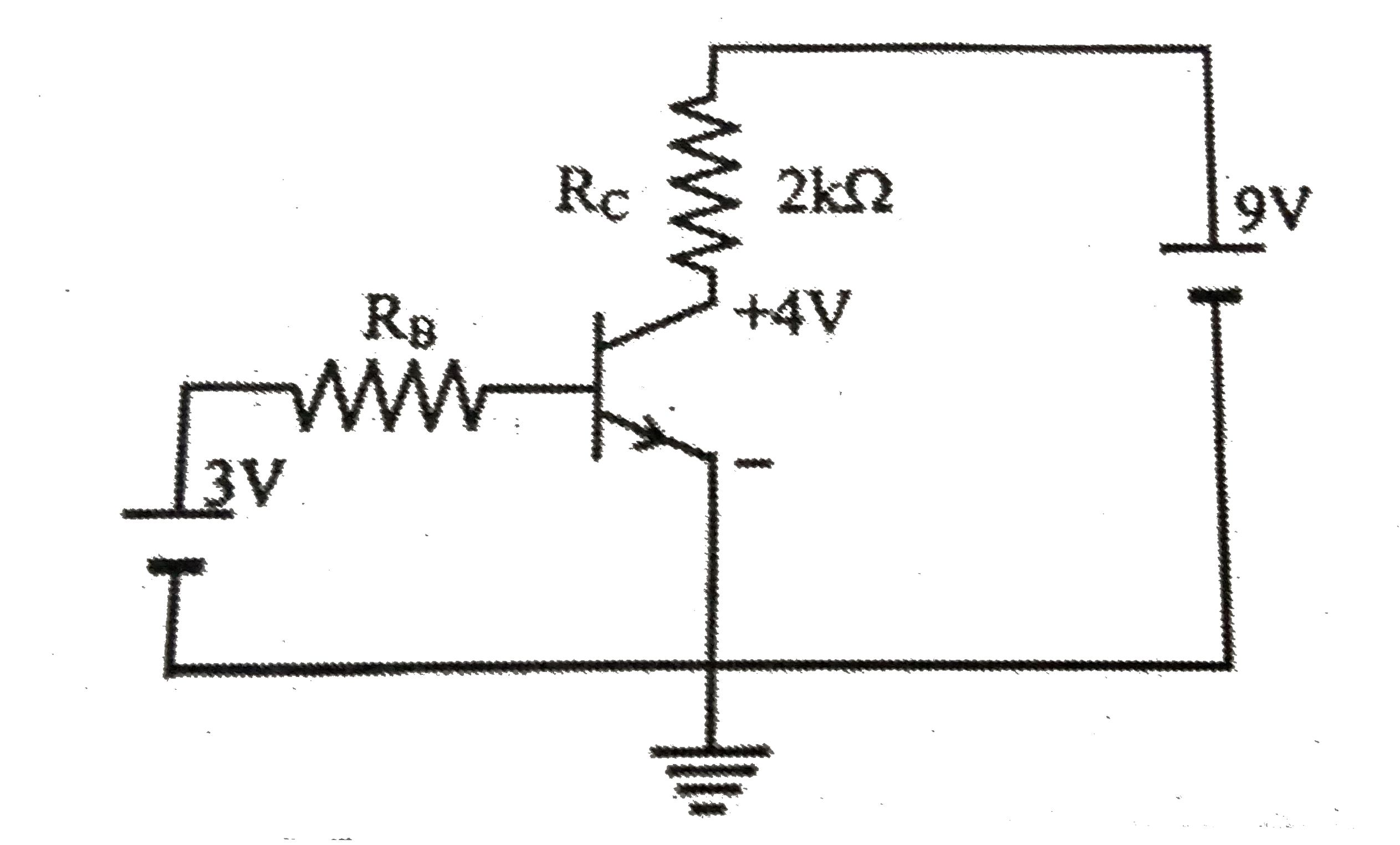
For the transistor circuit shown in figure , evaluate VE,RBandRE. Given IC=1mA,
VCE=3V,VBE=0.5V,VC=12Vandβ=1000
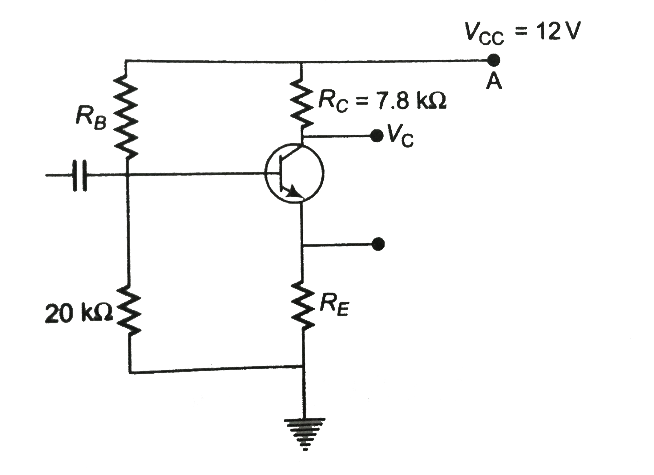
Let the current through the various arms be as shown in Fig.
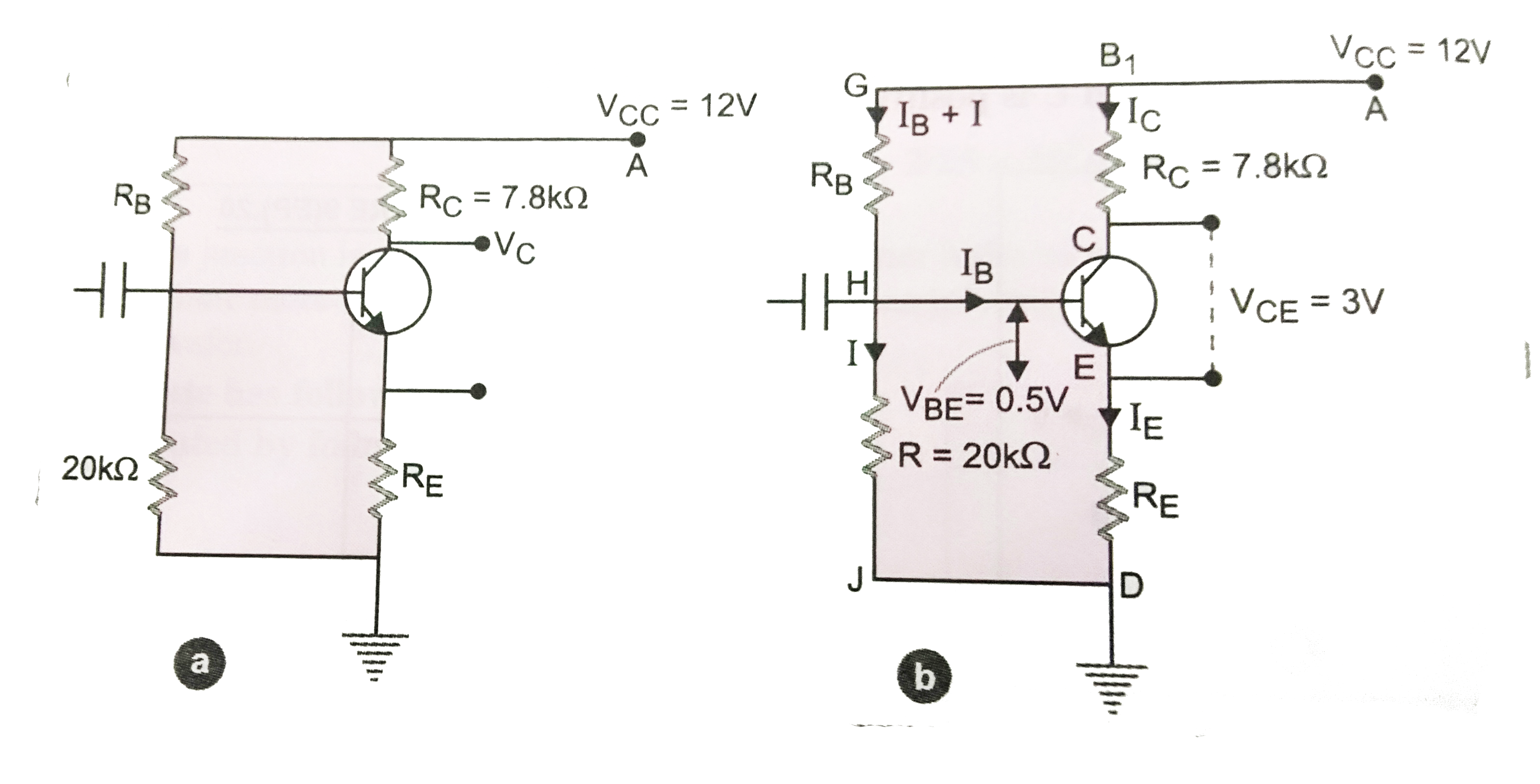
Here, IC=1mA=10−3A,VCE=3V,VBE=0.5V,β=100
IB=ICβ=10−3100=10−5A=.01mA
IE=IB+IC=10−5+10−3≈10−3A=IC
In closed circuit, AB1CEDA
I_C R_C+V_(CE)+I_(E)R_(E)=V_(C C)<br>orI_C R_C+I_C R_(E)=V_(C C)-V_(CE)=12-3=9V [ :' I_(E)=I_C]<br>orI_C(R_C+R_(E))=9 or R_C+R_(E)=9/10^(-3)=9kOmega<br>R_(E)=9kOmega-R_=9kOmega-7.8kOmega=1.2kOmega=1.2xx10^(3)Omega<br>V_(E)=I_(E)R_(E)=I_C R_(E)=10^(-3)xx(1.2xx10^(3))=1.2V<br>LetV=potentiald⇔erencebetweenHandJ,then<br>V=V_(E)+V_(BE)=1.2+0.5=1.7V<br>I=V/R=1.7/(20xx10^(3))A=0.085mA<br>NowV_(C C)=(I_B+I)R_B+V<br>orR_B=(V_(C C)-V)/(I_B+I)=((12-1.7)V)/((.01+0.085)mA)=(10.3V)/(0.095mA)=108.4kOmega
Topper's Solved these Questions
- ELECTRONIC DEVICESBook:PRADEEPChapter:ELECTRONIC DEVICESExercise:HIGHER ORDER THINKING SKILLS
Explore 1 Video
- ELECTRONIC DEVICESBook:PRADEEPChapter:ELECTRONIC DEVICESExercise:Exercise
Explore 312 Videos
- ELECTRONIC DEVICESBook:PRADEEPChapter:ELECTRONIC DEVICESExercise:VERY SHORT QUESTION ANSWER (NCERT)
Explore 1 Video
- ELECTROMAGNETIC WAVESBook:PRADEEPChapter:ELECTROMAGNETIC WAVESExercise:II Focus multiple choice question
Explore 5 Videos
- ELECTROSTATICSBook:PRADEEPChapter:ELECTROSTATICSExercise:ASSERTION-REASON TYPE QUESTIONS
Explore 2 Videos
Similar Questions
Knowledge Check
In the circuit shown in figure value of VR is
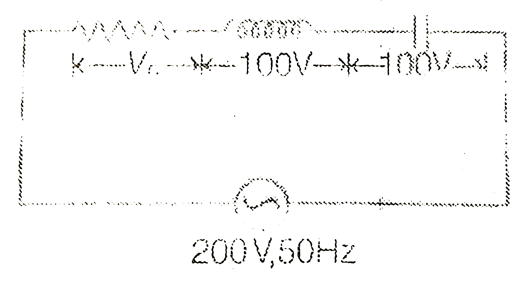 A400VB200VC300VDzero
In the circuit shown in the figure, the ratio of VB as VC is
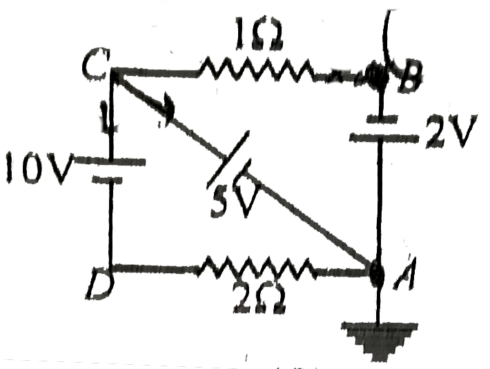 A−2/5B−5/2C1D1/3
Find VP−VQ in the circuit shown in figure.
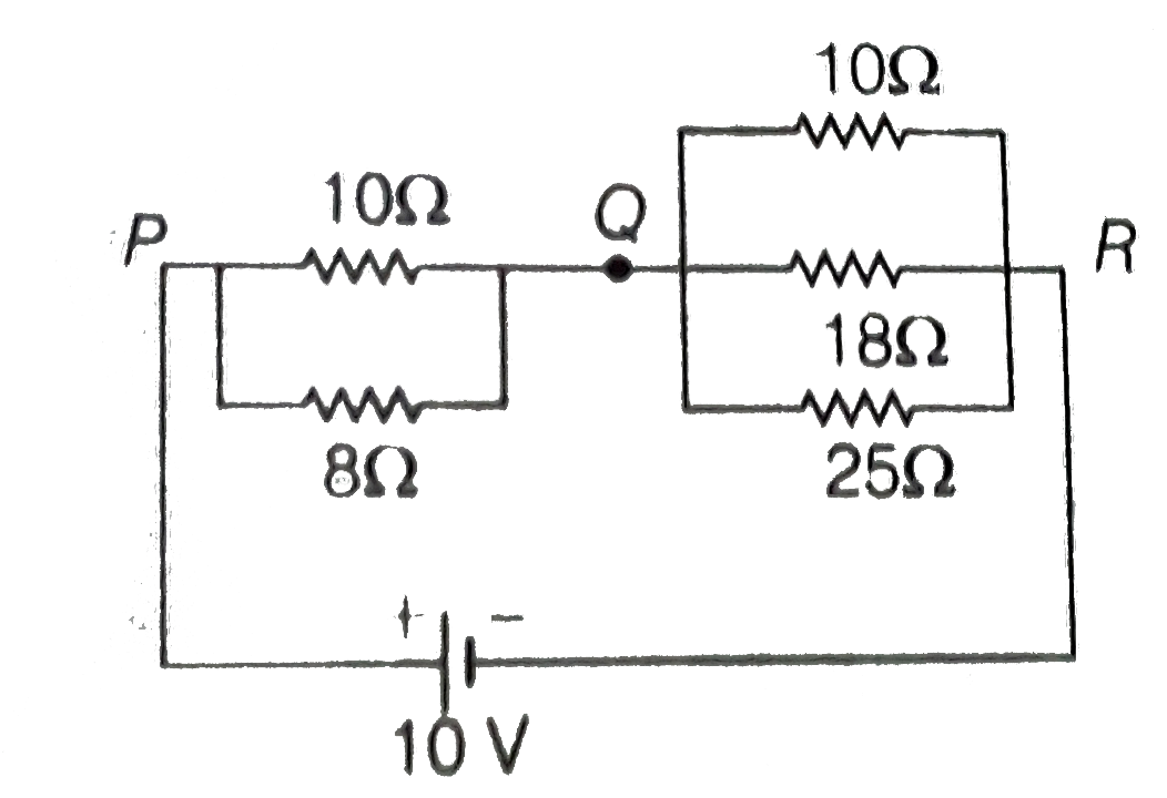 A6.68 VB8 VC4.65 VD7 V
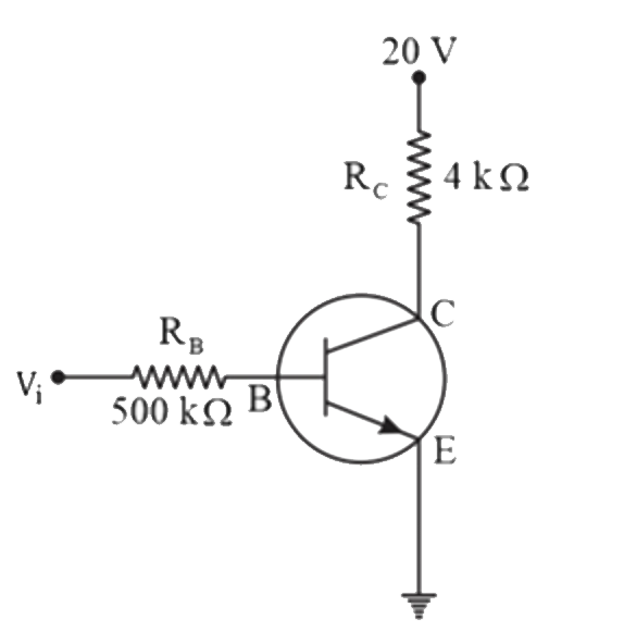
In the circuit shown in the figure, the input voltage Vi is 20V, VBE=0 and VCE=0. The values of IB, IC and β are given by
View SolutionIn the circuit shown in the figure, the input voltage Vi is 20V,VBE=0 and VCE=0. The values of IB,IC and β are given by:
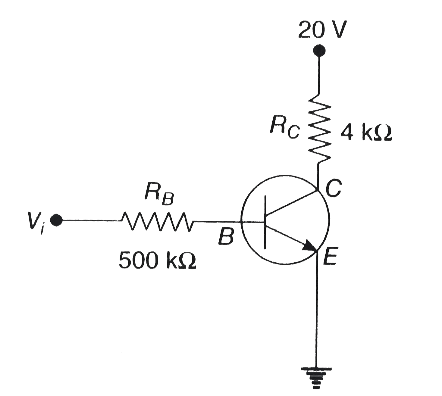
View SolutionIn the circuit shown in the figure, the input voltage Vi is 20V,VBE=0 and VCE=0. The values of IB,IC and β are given by:

View SolutionIn the circuit shows in the figure, the input voltage
Vi is 20 V, VBE=0 and VCE=0. The values of lB,lC and β are given by
View SolutionPassage I
An n-p-n transistor is used as a voltage amplifier in a commoin emitter circuit given
VC=8VIC=4mA
VCE=4V,
(VBE=0.6V,VBB=8V
βDc=200
The value of load resistqacne is
View Solution
