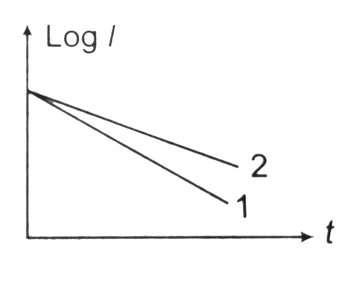
Assertion: Discharging graphs of two C.R. circuits having the same value of C is shown in figure. From the graph we can say that τC1>τC2
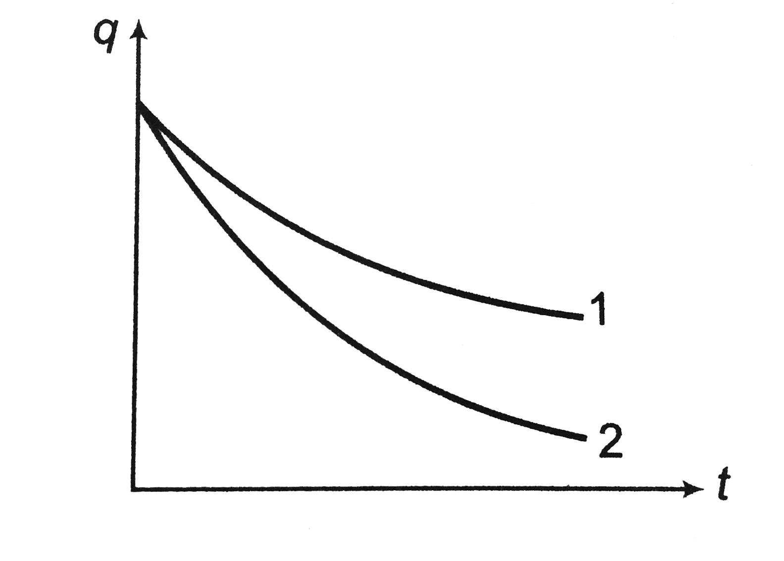
Reason: R1>R2
If both Assertion and Reason are true and the Reason is correct explanation of the Assertion.
If both Assertion and Reason are true but Reason is not the correct explanation of Assertion.
If Assertion is true, but the Reason is false.
If Assertion is false but the Reason is true.
The correct Answer is:A, B
In graph 1 , discharging is slow.
Hence τC1>τC2
Further,
τC=CR
τC∝R(asC=constant)
Topper's Solved these Questions
- CAPACITORSBOOK - DC PANDEY ENGLISHCHAPTER - CAPACITORSEXERCISE - OBJECTIVE_TYPE
1 Videos
- CAPACITORSBOOK - DC PANDEY ENGLISHCHAPTER - CAPACITORSEXERCISE - OBJECTIVE_TYPE
1 Videos
- ATOMSBOOK - DC PANDEY ENGLISHCHAPTER - ATOMSEXERCISE - MEDICAL ENTRANCES GALLERY
42 Videos
- COMMUNICATION SYSTEMBOOK - DC PANDEY ENGLISHCHAPTER - COMMUNICATION SYSTEMEXERCISE - Subjective
11 Videos
Similar Questions
In the L-C-R circuit as shown in figure,
View SolutionIn the circuit shown in figure , find the value of RC.
View SolutionDraw E-r and V-r graphs due to two charged spherical shells as shown in figure (along the line between C and ∝)
View SolutionIn the circuit shown in fig. (a), final the value of RC.
View SolutionIn the circuit shown in the figure XL=XC2)=R the peck value current i0 is
View SolutionAssertion: In the part of the circuit shown in figure, maximum power is produced across R.
Reason : Power P=V2R
View SolutionCurrent growth in two L-R circuits (b) and (c ) as shown in figure (a). Let L1,L2,R1 and R2 be the corresponding values in two circuits. Then

View SolutionAssertion: At resonance, power factor of L-C-R series circuit is 1.
Reason: At resonance, XC=XL
View SolutionTwo concentric spherical shells of radii R and 2R have charges Q and 2Q as shown in figure

If we draw a graph between potential V and distance r from the centre, the graph will be like
View SolutionA graph between current and time during charging of a capacitor by a battery in series with a resistor is shown. The graphs are drawn for two circutis. R1,R2,C1,C2 and V1,V2 are the values of resistance, capacitance and EMF of the cell in the two circuits. If only two parameters (out of resistance, capacitance, EMF) are different in the two circuits. What may be the correct options (s) ?
View Solution
