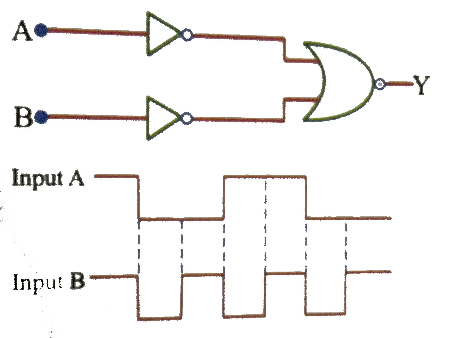
The logic circuit shown below has the input waveforms 'A' and 'B' as shown. Pick out the current output waveform.
 Solution in Telugu


The correct Answer is:D
Step by step video, text & image solution for The logic circuit shown below has the input waveforms 'A' and 'B' as shown. Pick out the current output waveform. by Physics experts to help you in doubts & scoring excellent marks in Class 12 exams.
Updated on:21/07/2023Topper's Solved these Questions
- SEMICONDUCTOR DEVICESBook:AAKASH SERIESChapter:SEMICONDUCTOR DEVICESExercise:EXERCISE - IA
Explore 13 Videos
- RAY OPTICSBook:AAKASH SERIESChapter:RAY OPTICSExercise:PROBLEMS ( LEVEL-II)
Explore 50 Videos
- UNITS AND MEASUREMENTBook:AAKASH SERIESChapter:UNITS AND MEASUREMENTExercise:PRACTICE EXERCISE
Explore 45 Videos
Similar Questions
The element that can be used as acceptor impurity to dope silicon is
View SolutionTwo plane mirrors are combined to each other such that one is in y-z plane and the other is in X-z plane. A ray of light travelling along a vector ˆi+ˆi+ˆk is incident on the first mirror. Find the unit vector in the direction of emergent ray after successive reflections through both the mirrors.
View SolutionThe ratio of S.I. unit of universal gravitational constant to C.G.S. unit is
View SolutionThe logic circuit shown belows has the input waveforms 'A' and 'B' as shown. Pick out the correct output waveform
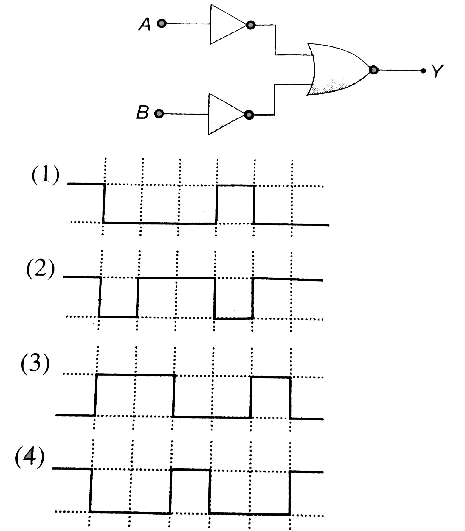
View SolutionThe logic circuit shown below has the input waveforms 'A' and 'B' as shown. Pick out the correct output waveform .
View SolutionThe logic circuit shown below has the input waveform 'A' and 'B' as shown. Pick out the correct output waveform Output is :-
View SolutionThe logic circuit shown has the input waveforms 'A' and 'B' as shown. Pick out the CORRECT output waveform:-
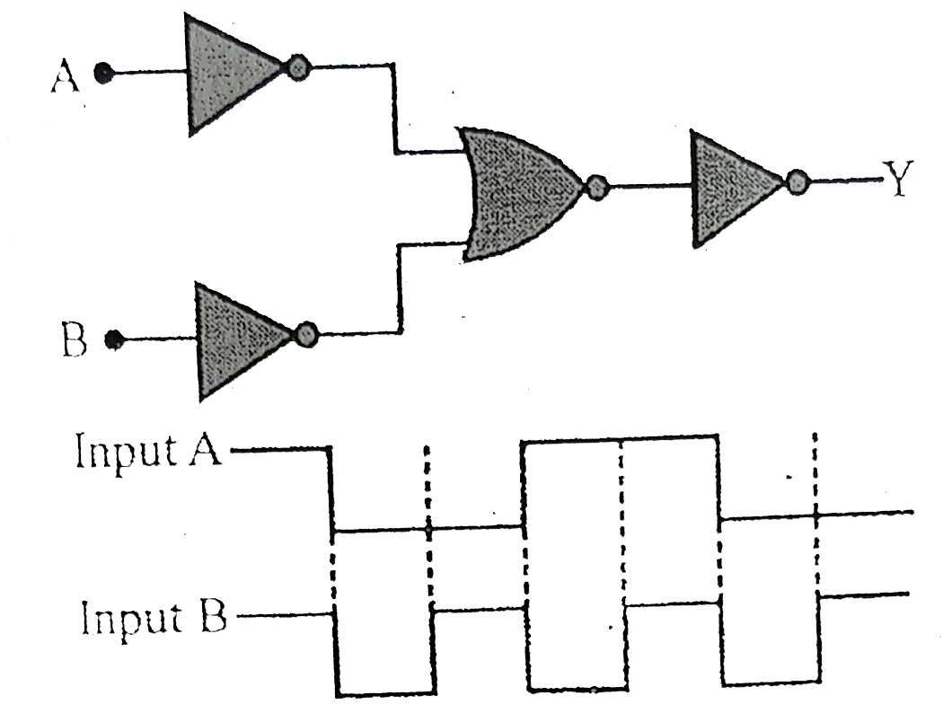
View SolutionThe logic circuit shown below has the input waveforms ‘A’ and ‘B’ as shown. Pick out the correct output waveform
View SolutionTwo input waveforms A and B shown in fig (a) are applied to an AND gate.Write the output waveform.
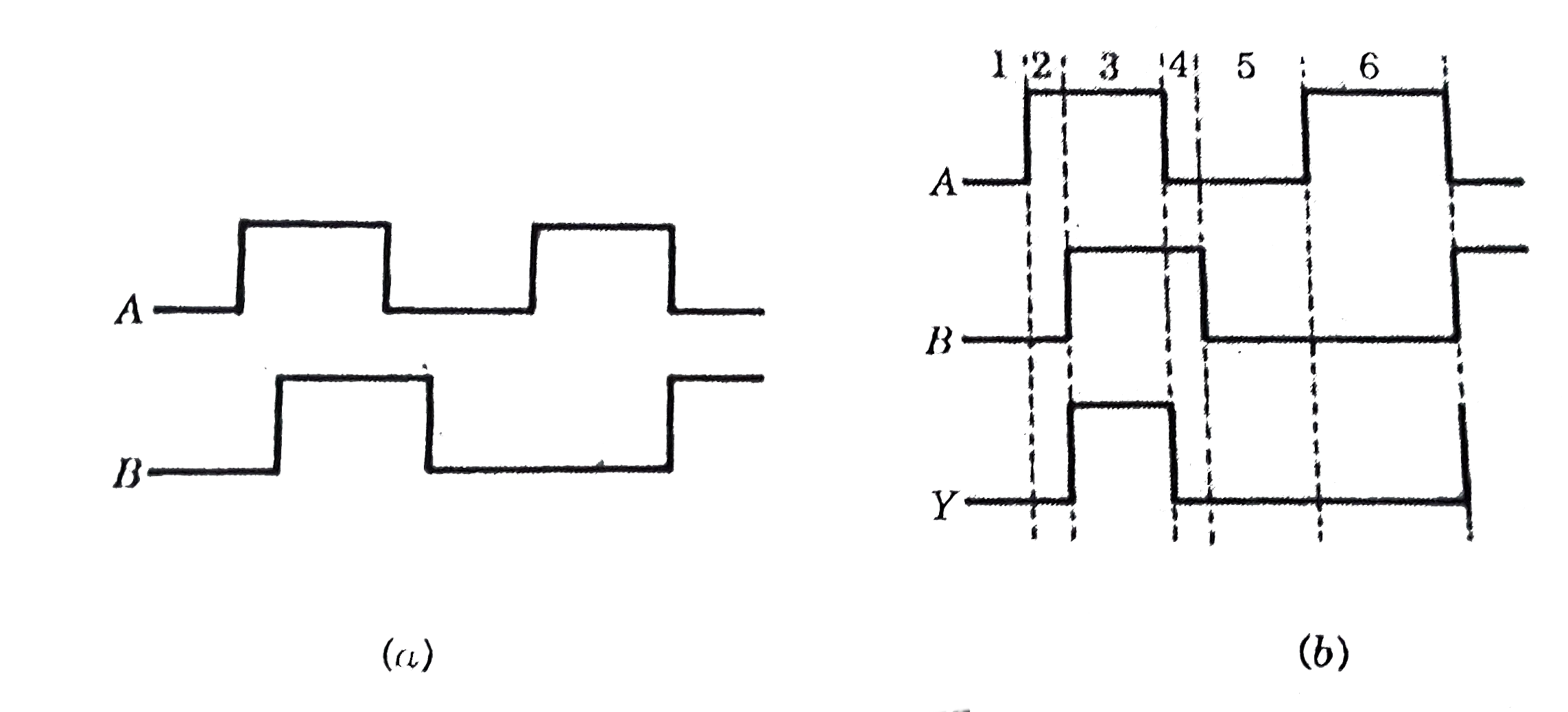
View SolutionThe logic circuit shown below has the inputs waveforms A and B as shown. Pick out the correct output waveform.
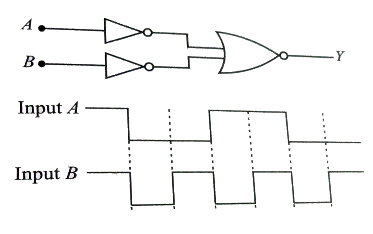
View SolutionThe following figure shows a logic gate circuit with two inputs A and B and the output C. The voltage waveforms of A, B and C are as shown below.
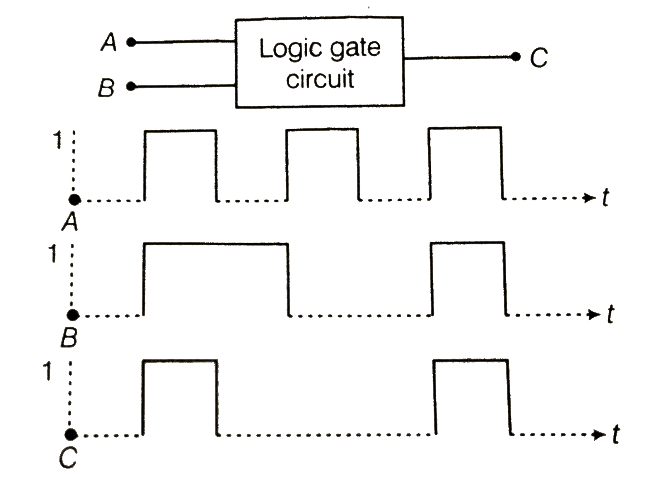
The logic circuit gate is
View SolutionThe logic circuit shown has the input waveforms 'A' and 'B' as shown. Pick out the correct output waveform
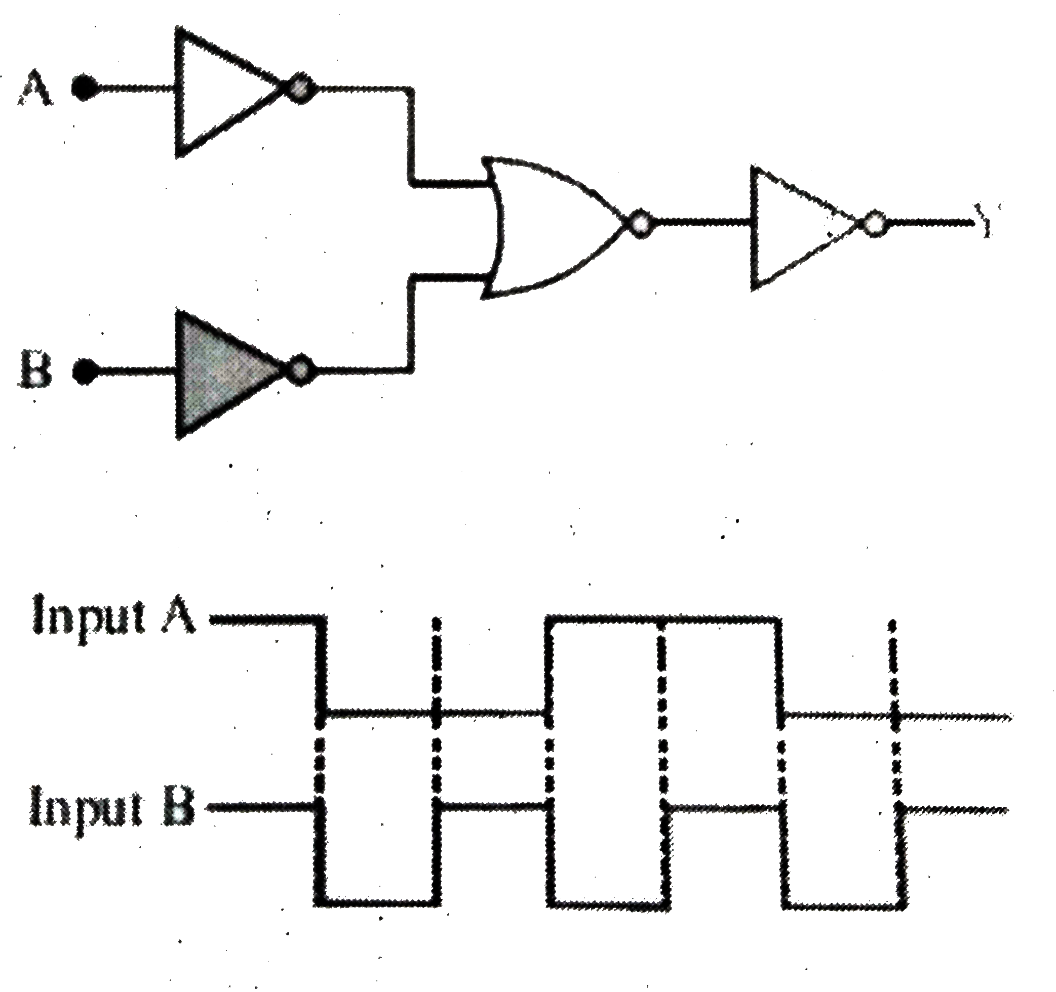
View SolutionThe logic circuit shown below has the input waveform 'A' and 'B' as shown . Pick out the correct output waveform .
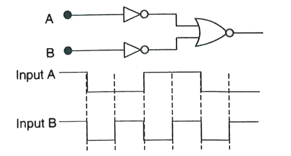
output is :
View SolutionThe following shows a logic gate circuit with two inputs A and B and the output C. The voltage waveforms of A, B and C are as shown below.
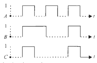
The logic circuit gate is
View SolutionThe logic circuit shown below has the input waveforms 'A' and 'B' as shown. Pick out the correct output waveform
 .
.
View Solution

