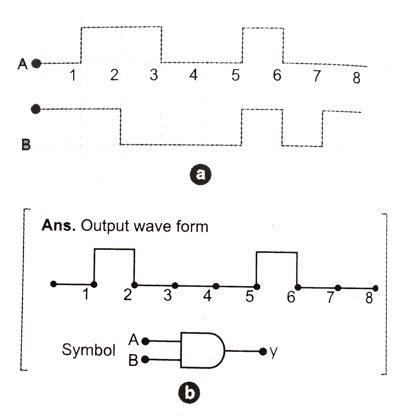
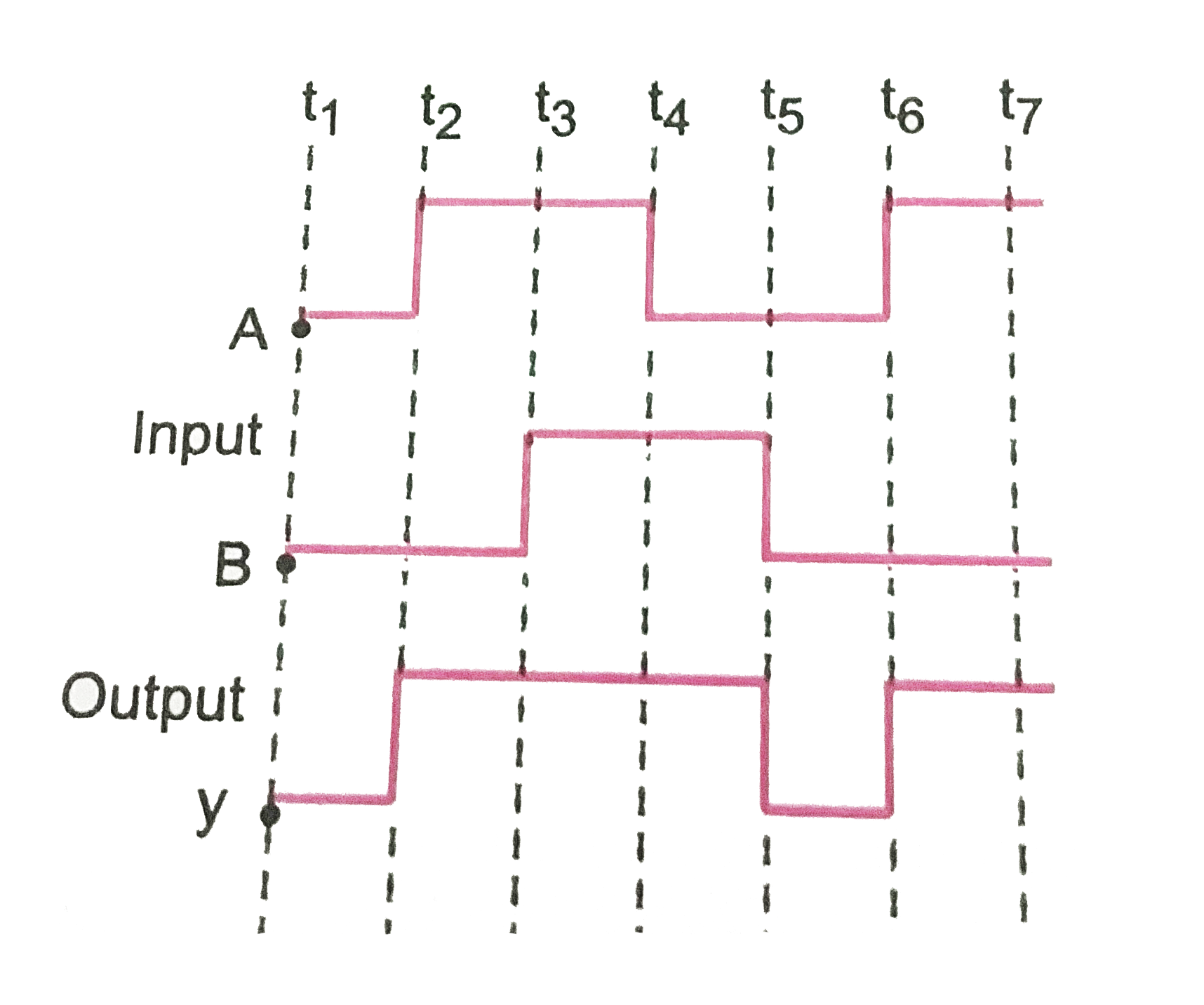
Two input waveforms A and B shown in fig (a) are applied to an AND gate.Write the output waveform.
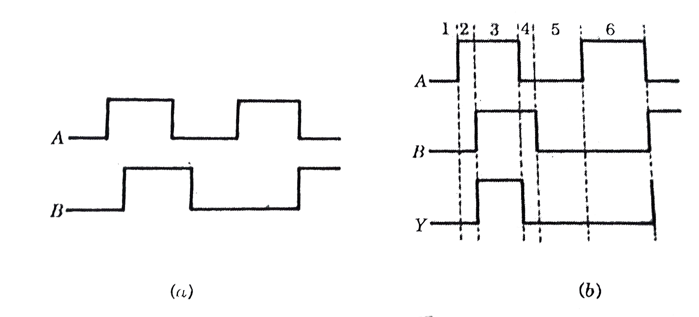
The correct Answer is:NA
Step by step video, text & image solution for Two input waveforms A and B shown in fig (a) are applied to an AND gate.Write the output waveform. by Physics experts to help you in doubts & scoring excellent marks in Class 12 exams.
Updated on:21/07/2023Topper's Solved these Questions
Similar Questions
Knowledge Check
In the given circuit as shown the two input waveform A and B are applied simultaneously. The resultant waveform Y is
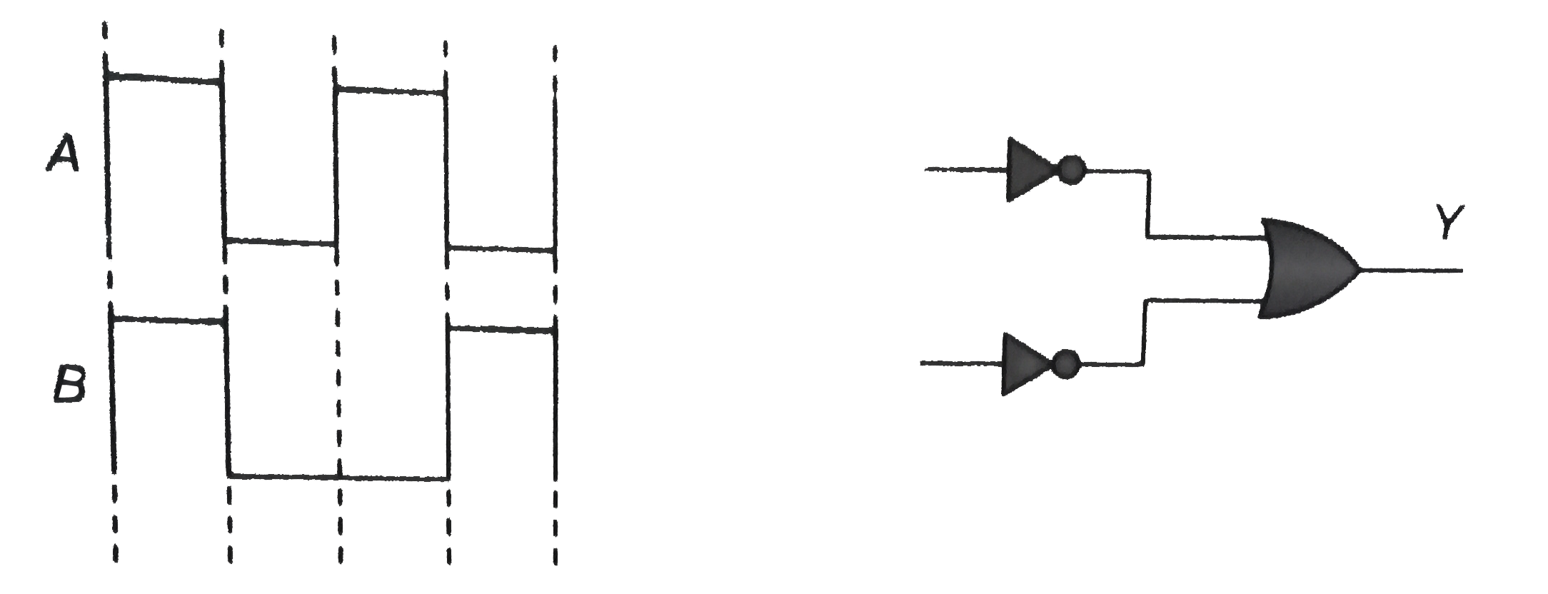 A
A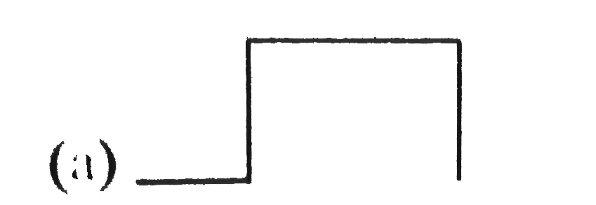 B
B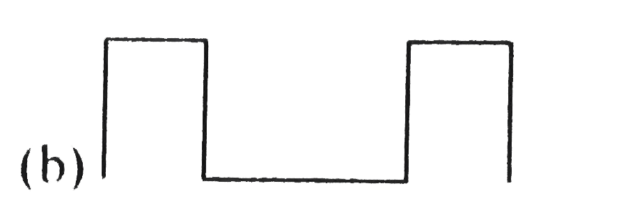 C
C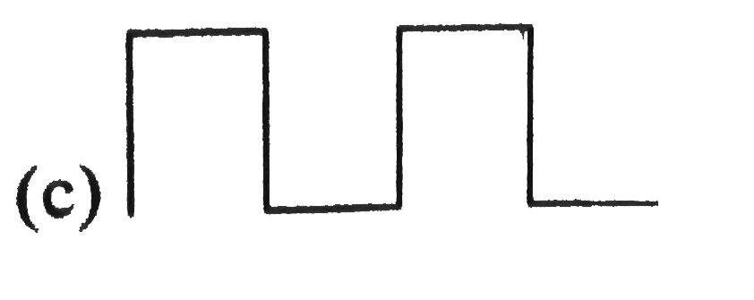 D
D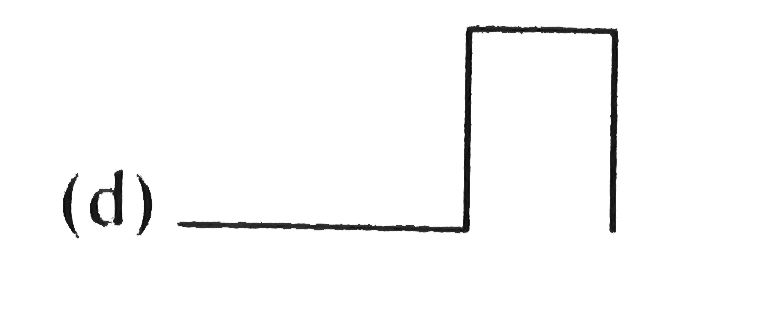
The logic circuit shown below has the input waveform 'A' and 'B' as shown. Pick out the correct output waveform
_E01_490_Q01.png)
Output is :-A_E01_490_O01.png) B
B_E01_490_O02.png) C
C_E01_490_O03.png) D
D_E01_490_O04.png)
Two signal A and B shown in the Fig. are used as two inputs of a NAND gate. Draw its output wave form. Give the logic symbol of NAND gate.
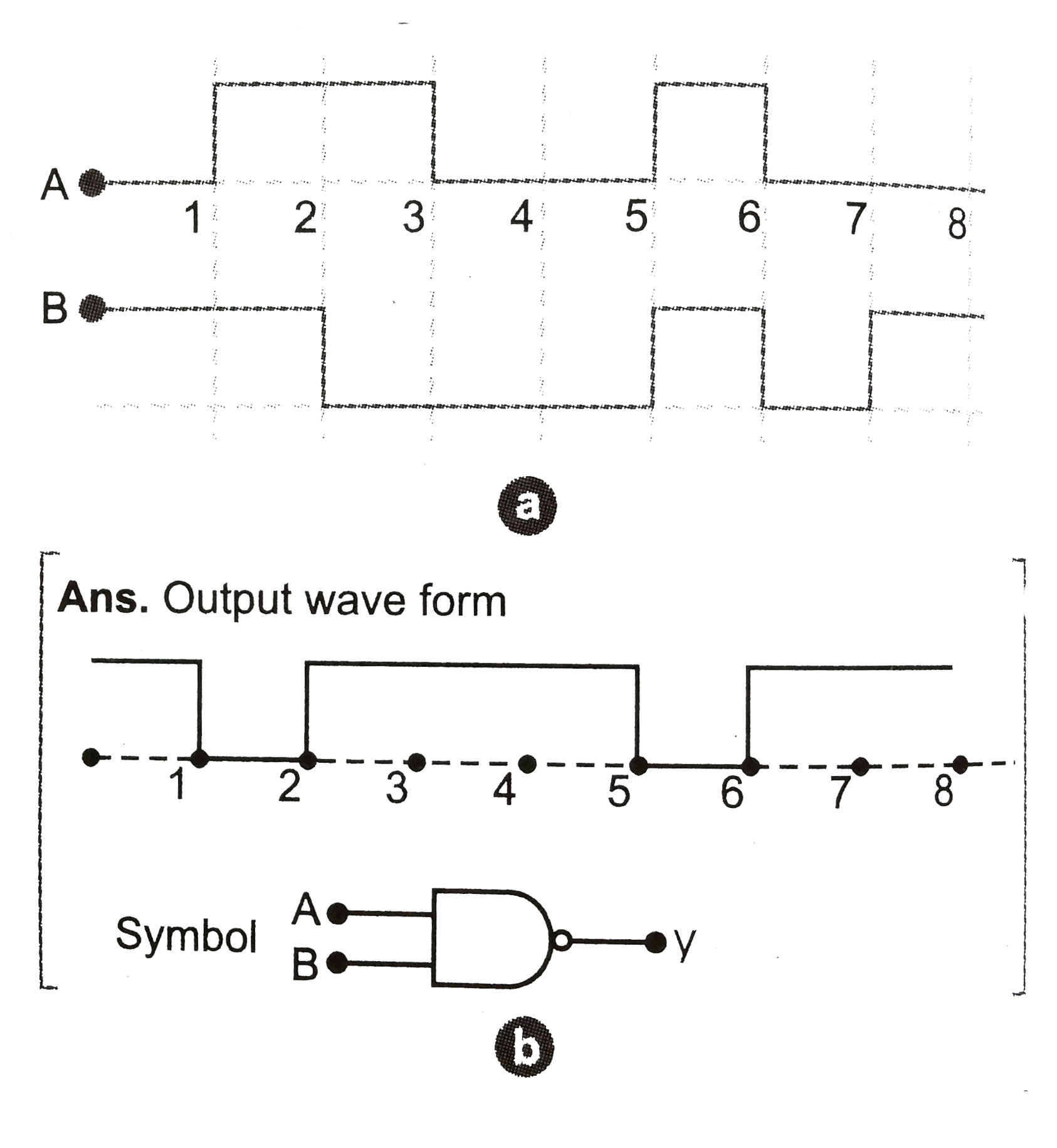
View SolutionThe Fig shown input waveforms A and B to a logic gate. Draw the output waveform for an OR gate. Write the truth table for this logic gate and draw its logic symbol.
View SolutionInput waveforms A and B as shown in Fig-l are applied to the combination of gates as shown in Fig-ll. Which of the waveforms shown in Fig.(i) to (iv) correctly represents the output waveform?
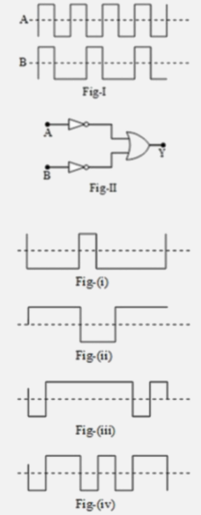
View SolutionInput waveforms A and B as shown in Fig-l are applied to the combination of gates as shown in Fig-ll. Which of the waveforms shown in Fig.(i) to (iv) correctly represents the output waveform?

View Solution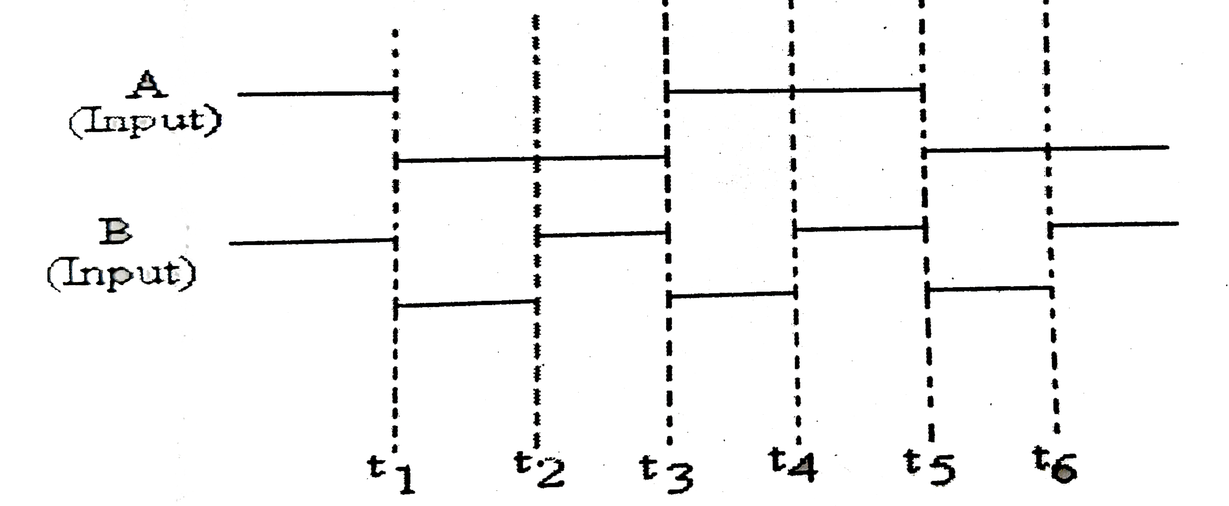
The give inputs A, B are fed to a 2-input NAND gate. Draw the output wave form of the gate.
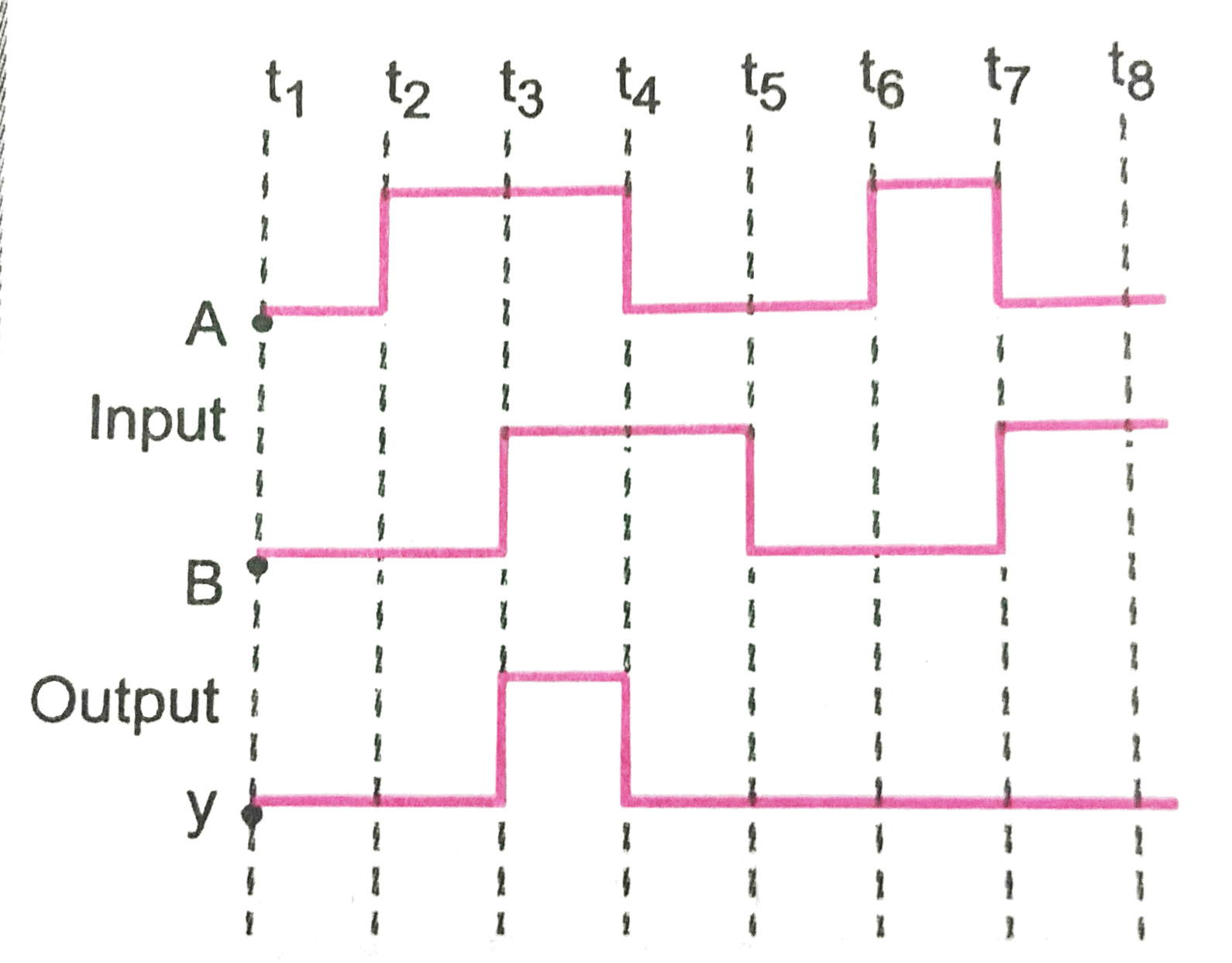
View SolutionThe Fig.shows the input wavwforms A and B for 'AND' gate. Draw the output waveform and write the truth table for this logic gate.
View Solution

