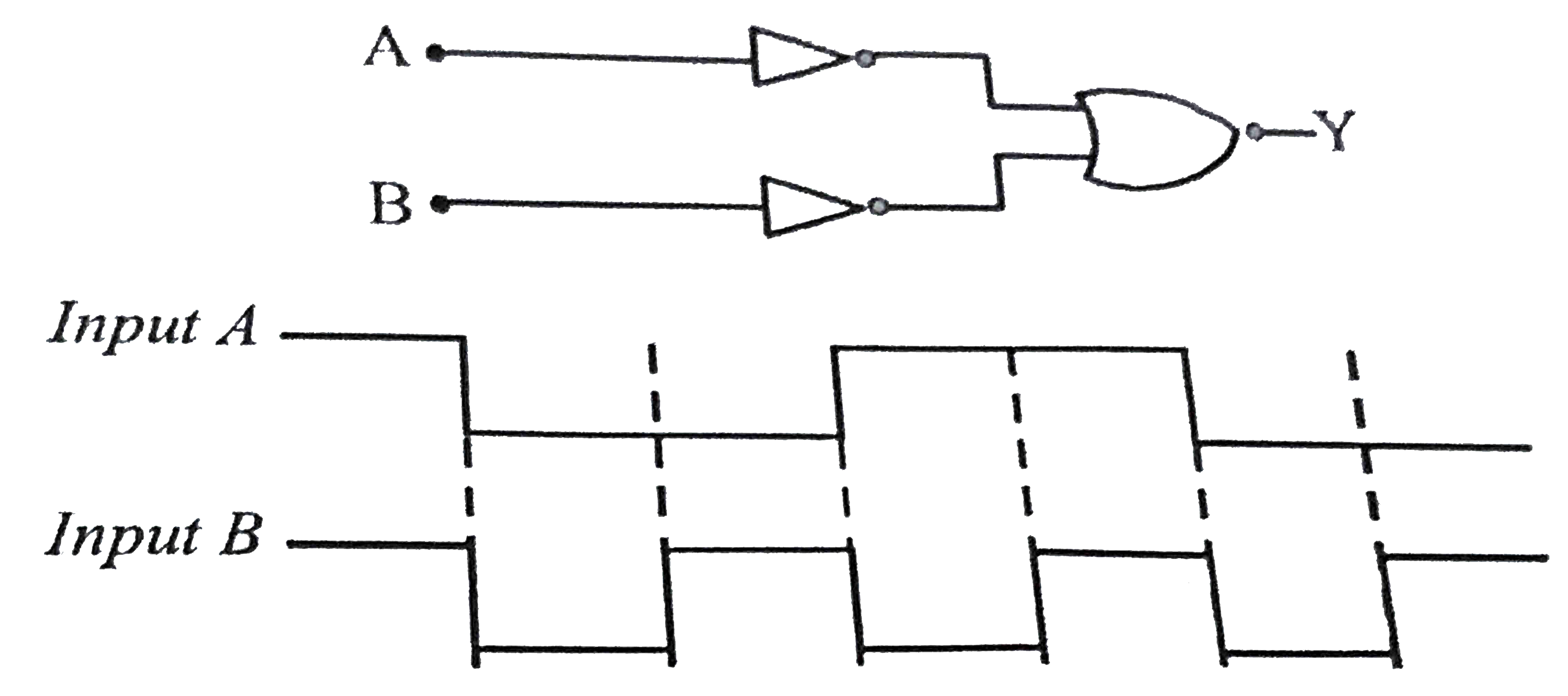
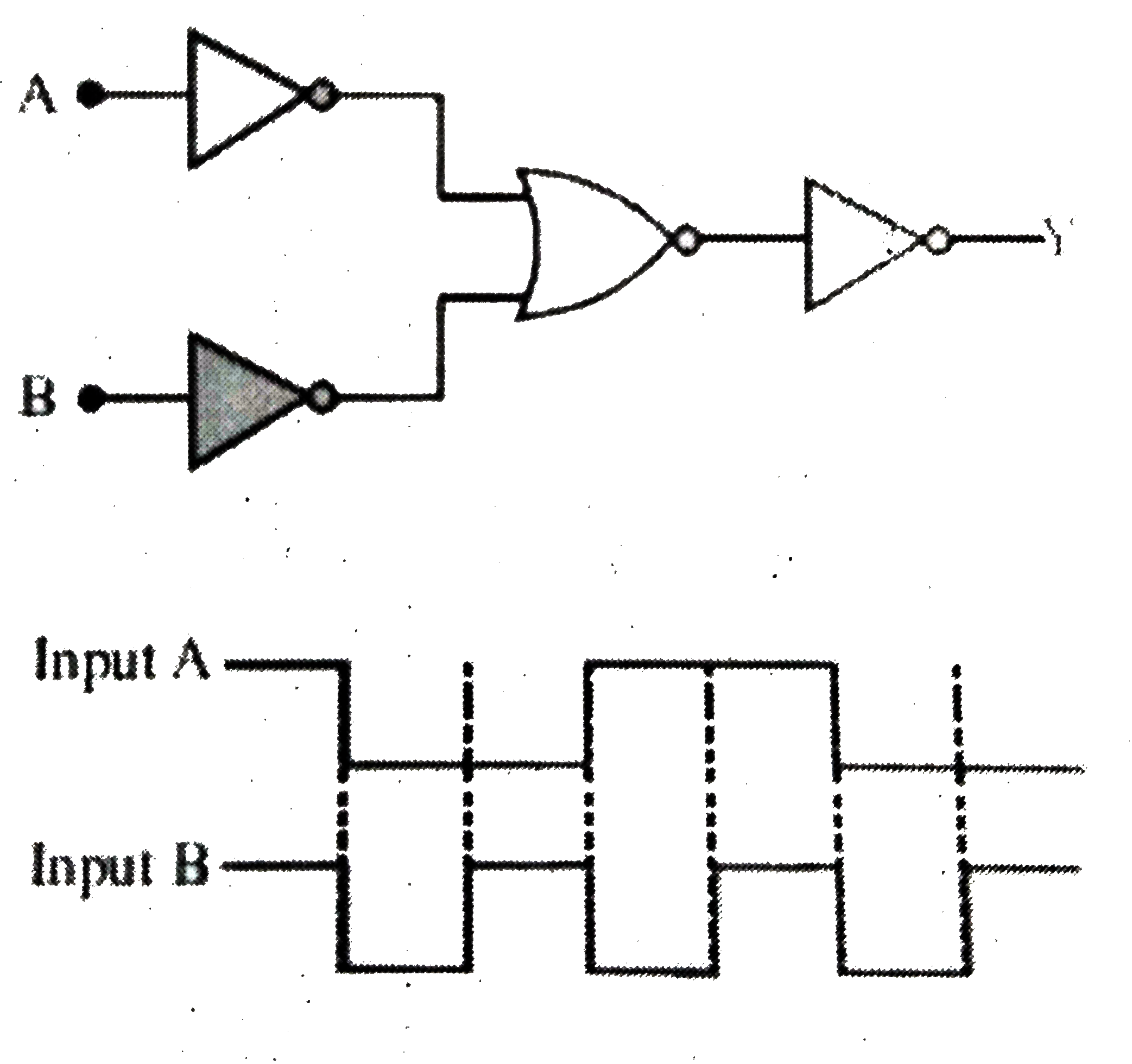
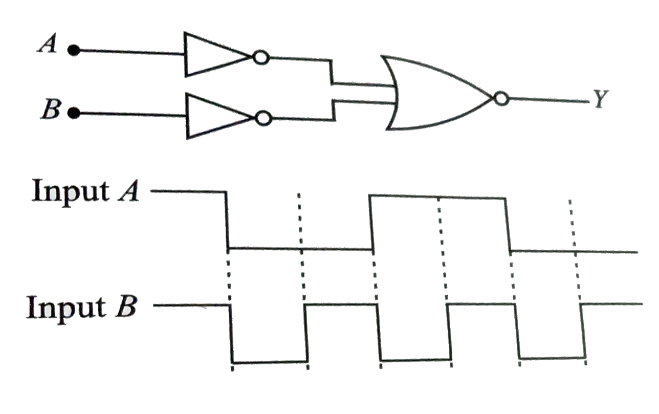
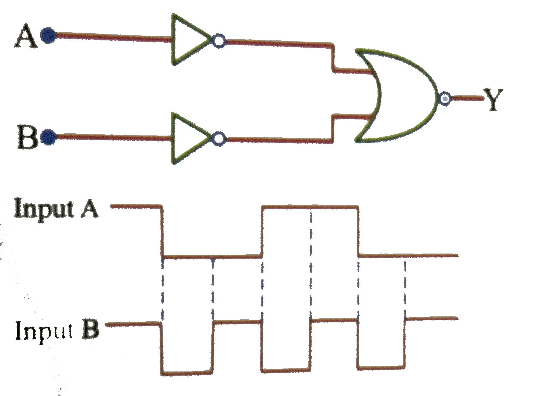
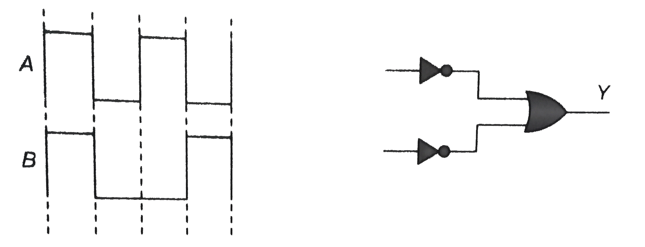
The logic circuit shown below has the inputs waveforms A and B as shown. Pick out the correct output waveform.
A

B

C

D

Video Solution
Text Solution
The correct Answer is:A

The output of the circuit is
=Y=¯¯¯¯¯¯¯¯¯¯¯¯¯¯¯A+¯¯¯B=¯¯¯¯¯¯¯A.¯¯¯¯¯¯B=A.B (By de Morgan's theorem)
It is the Boolean expression of AND gate.
The output waveform corresponding to given input waveforms A and B is as shown below

|
Topper's Solved these Questions
- SEMICONDUCTOR ELECTRONICS : MATERIALS , DEVICES AND SIMPLE CIRCUITS BOOK - NCERT FINGERTIPSCHAPTER - SEMICONDUCTOR ELECTRONICS : MATERIALS , DEVICES AND SIMPLE CIRCUITS EXERCISE - Higher Order Thinking Skills
8 Videos
- SEMICONDUCTOR ELECTRONICS : MATERIALS , DEVICES AND SIMPLE CIRCUITS BOOK - NCERT FINGERTIPSCHAPTER - SEMICONDUCTOR ELECTRONICS : MATERIALS , DEVICES AND SIMPLE CIRCUITS EXERCISE - NCERT Exemplar
8 Videos
- SEMICONDUCTOR ELECTRONICS : MATERIALS , DEVICES AND SIMPLE CIRCUITS BOOK - NCERT FINGERTIPSCHAPTER - SEMICONDUCTOR ELECTRONICS : MATERIALS , DEVICES AND SIMPLE CIRCUITS EXERCISE - Junction Transistor
33 Videos
- RAY OPTICS AND OPTICAL INSTRUMENTSBOOK - NCERT FINGERTIPSCHAPTER - RAY OPTICS AND OPTICAL INSTRUMENTSEXERCISE - Assertion And Reason
15 Videos
- WAVE OPTICSBOOK - NCERT FINGERTIPSCHAPTER - WAVE OPTICSEXERCISE - Assertion And Reason
15 Videos
Similar Questions
Knowledge Check
The logic circuit shown below has the input waveforms A and B as shown. Pick out the correct out put waveform.
 A
A B
B C
C D
D
The logic circuit shown below has the input waveform 'A' and 'B' as shown. Pick out the correct output waveform
_E01_490_Q01.png)
Output is :-A_E01_490_O01.png) B
B_E01_490_O02.png) C
C_E01_490_O03.png) D
D_E01_490_O04.png)
The logic circuit shown below has the input waveforms 'A' and 'B' as shown. Pick out the correct output waveform
 .A
.A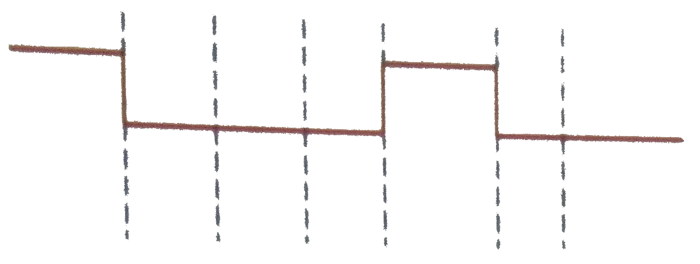 B
B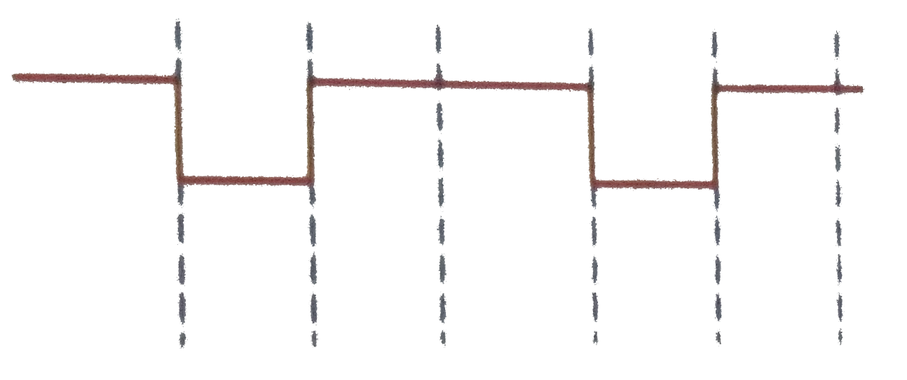 C
C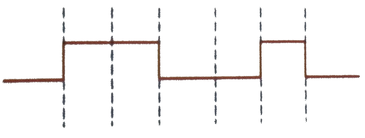 D
D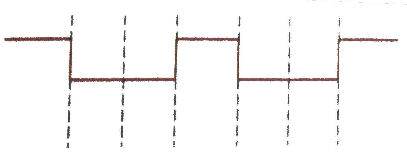
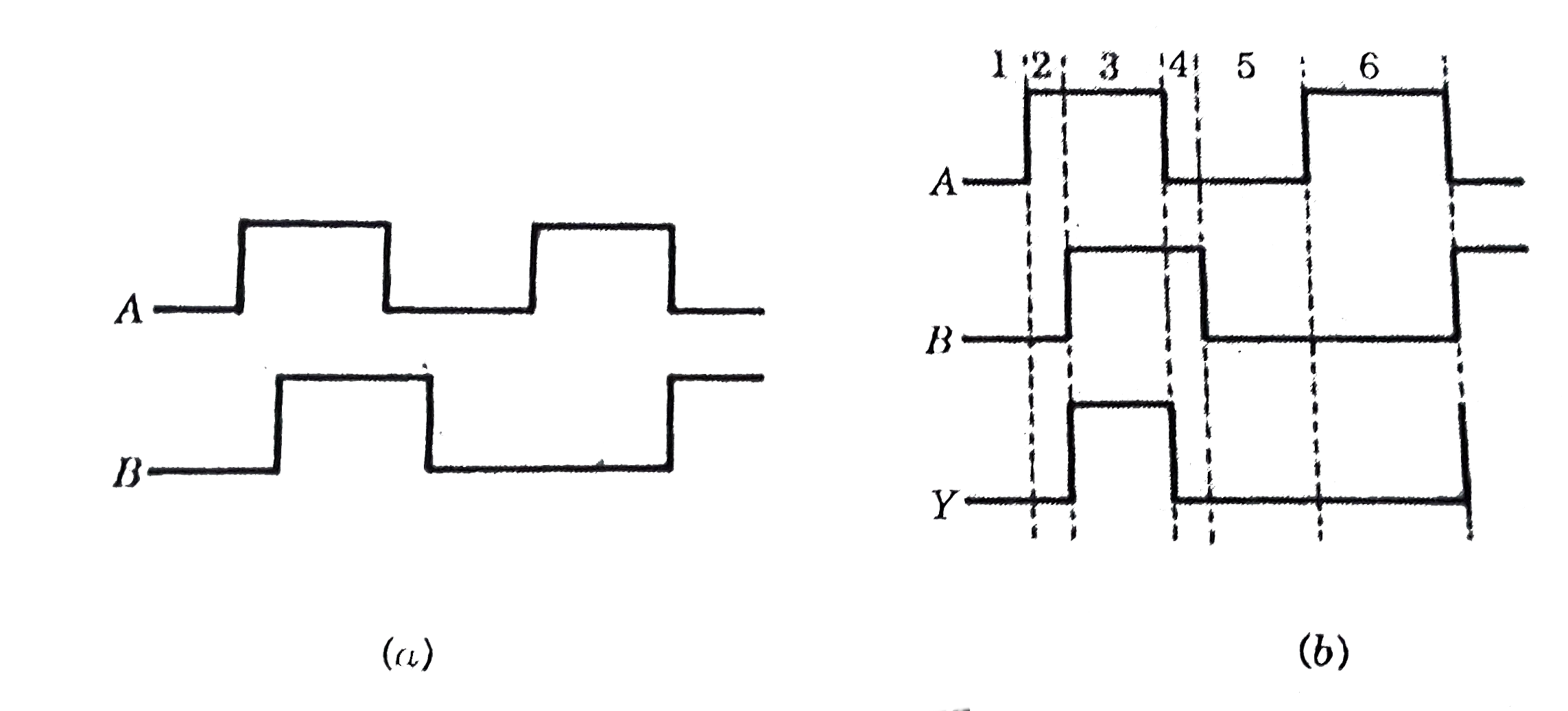
Two input waveforms A and B shown in fig (a) are applied to an AND gate.Write the output waveform.
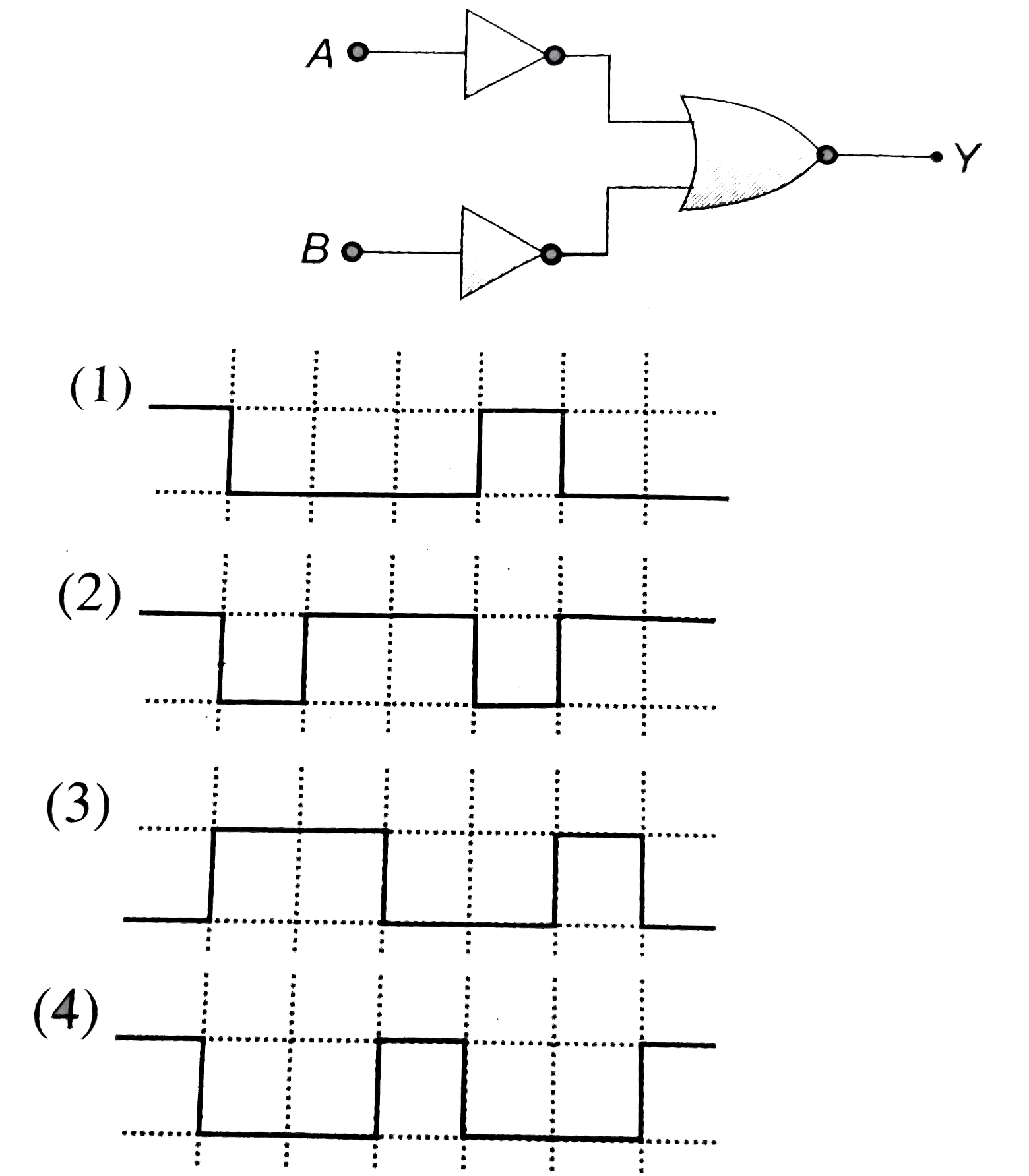
View SolutionThe logic circuit shown belows has the input waveforms 'A' and 'B' as shown. Pick out the correct output waveform
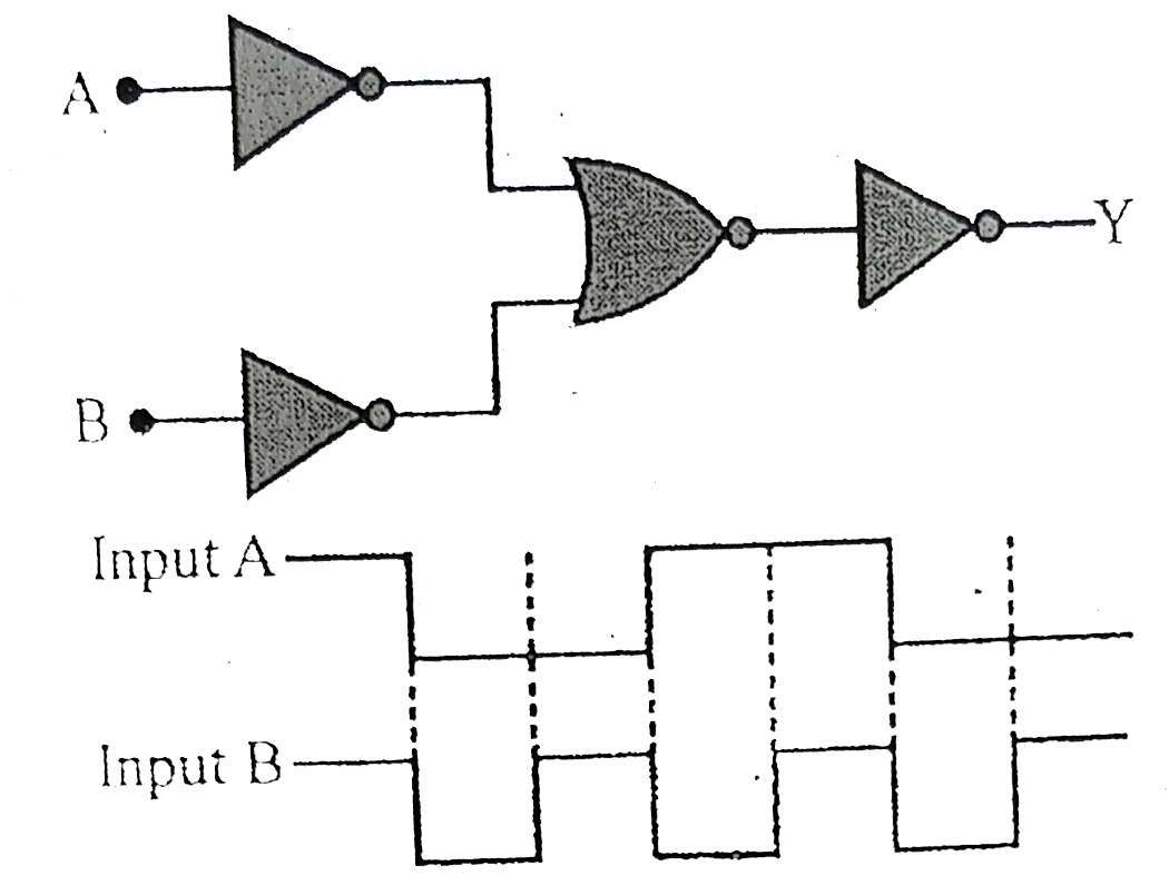
View SolutionThe logic circuit shown has the input waveforms 'A' and 'B' as shown. Pick out the CORRECT output waveform:-
View SolutionIn the given circuit as shown the two input waveform A and B are applied simultaneously. The resultant waveform Y is
View SolutionOutput of the circuit shown below will be

View Solution

