The output (X) of the logic circuit shown in figure will be
 Solution in Telugu
X=¯¯¯¯¯¯¯A.¯¯¯¯¯¯B
X=¯¯¯¯¯¯¯¯A.B
X = A.B
X=¯¯¯¯¯¯¯¯¯¯¯A+B
The correct Answer is:C
Step by step video, text & image solution for The output (X) of the logic circuit shown in figure will be by Physics experts to help you in doubts & scoring excellent marks in Class 12 exams.
Topper's Solved these Questions
- BOOK - AAKASH SERIESCHAPTER - SEMICONDUCTOR DEVICESEXERCISE - EXERCISE - IA13videos
SEMICONDUCTOR DEVICES
- BOOK - AAKASH SERIESCHAPTER - RAY OPTICSEXERCISE - PROBLEMS ( LEVEL-II)50videos
RAY OPTICS
- BOOK - AAKASH SERIESCHAPTER - UNITS AND MEASUREMENTEXERCISE - PRACTICE EXERCISE45videos
UNITS AND MEASUREMENT
Similar Questions
The element that can be used as acceptor impurity to dope silicon is
01:13View SolutionTwo plane mirrors are combined to each other such that one is in y-z plane and the other is in X-z plane. A ray of light travelling along a vector ˆi+ˆi+ˆk is incident on the first mirror. Find the unit vector in the direction of emergent ray after successive reflections through both the mirrors.
01:44View SolutionThe ratio of S.I. unit of universal gravitational constant to C.G.S. unit is
02:22View SolutionThe output (X) of the logic circuit shown in figure will be
03:15View SolutionThe following figure shows a logic gate circuit with two inputs A and B and the output C. The voltage waveforms of A, B and C are as shown below.
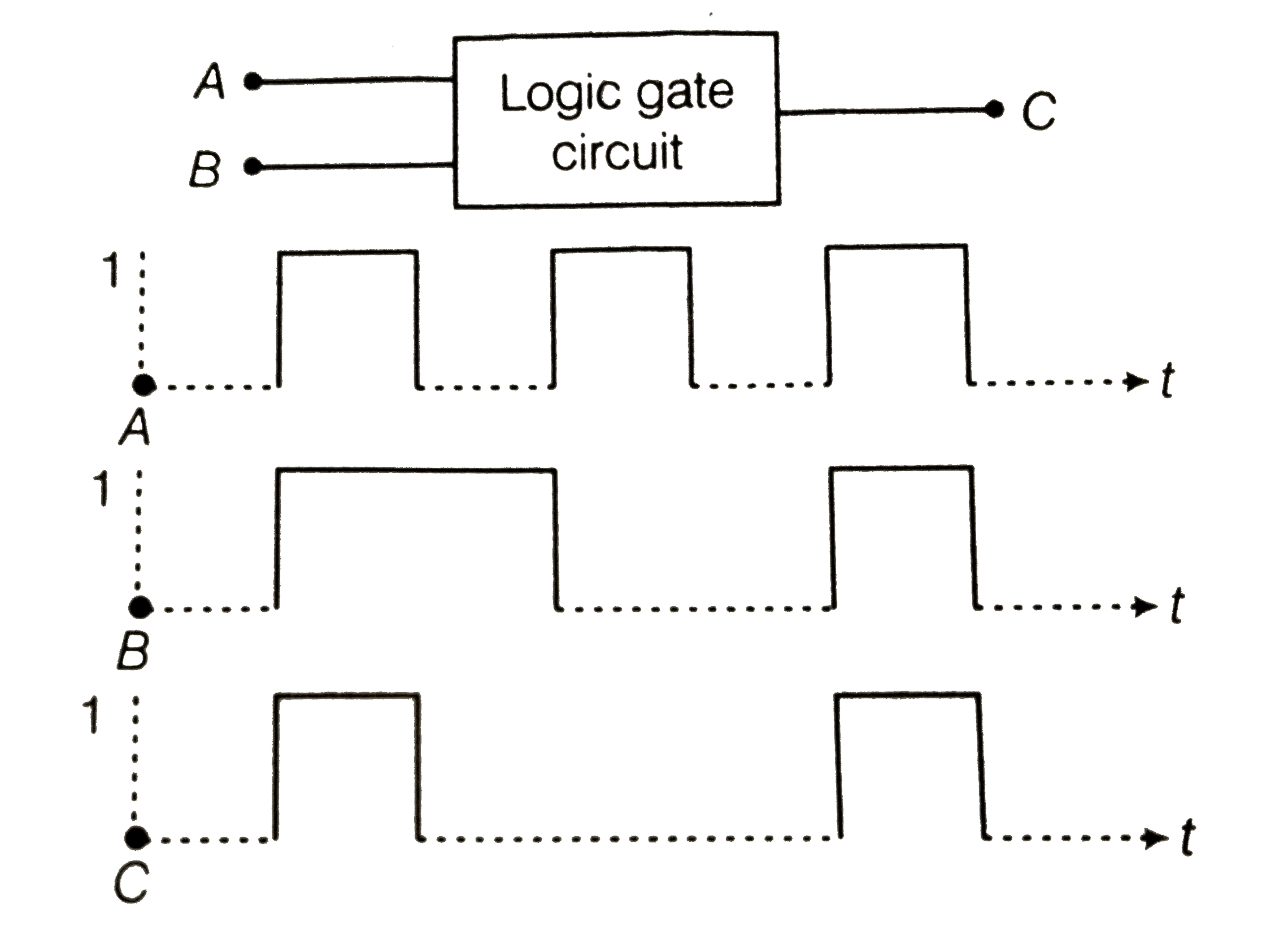
The logic circuit gate is02:01View SolutionThe output (X) of the logic circuit shown in figure will be
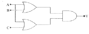
04:04View Solutionचित्र में प्रदर्शित लॉजिक परिपथ के निर्गम के लिए बुलियन व्यंजक होगा-
 02:55View Solution
The output (X) of the logic circuit shown in figure will be
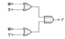
01:54View Solutionएक तार्किक परिपथ को चित्र में दर्शाया गया है। परिपथ से निर्गत F किससे प्रदर्शित होगा
 01:27View Solution
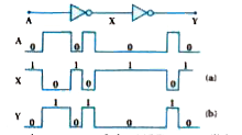
A logic circuit is shown in the diagram. Draw the output signal at the point X and Y for the input signal shown in the figure at point A.
 01:27View Solution
A circuit of logic gte made from two AND gate is shown in following figure. Draw output waves for point X. For A and for Y.
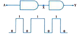 01:09View Solution
चित्र में दिखाए गए लॉजिक परिपथ का निर्गत सबसे उचित प्रदर्शित किया जाता है
 01:12View Solution
The output Y of the logic circuit as shown in figure is
03:27View SolutionThe output Y of the logic circuit as shown in figure is best represents as
01:44View SolutionThe output (X) of the logic circuit shown in figure will be
01:46View Solution

