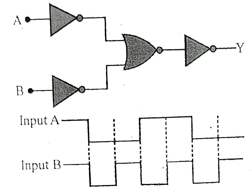
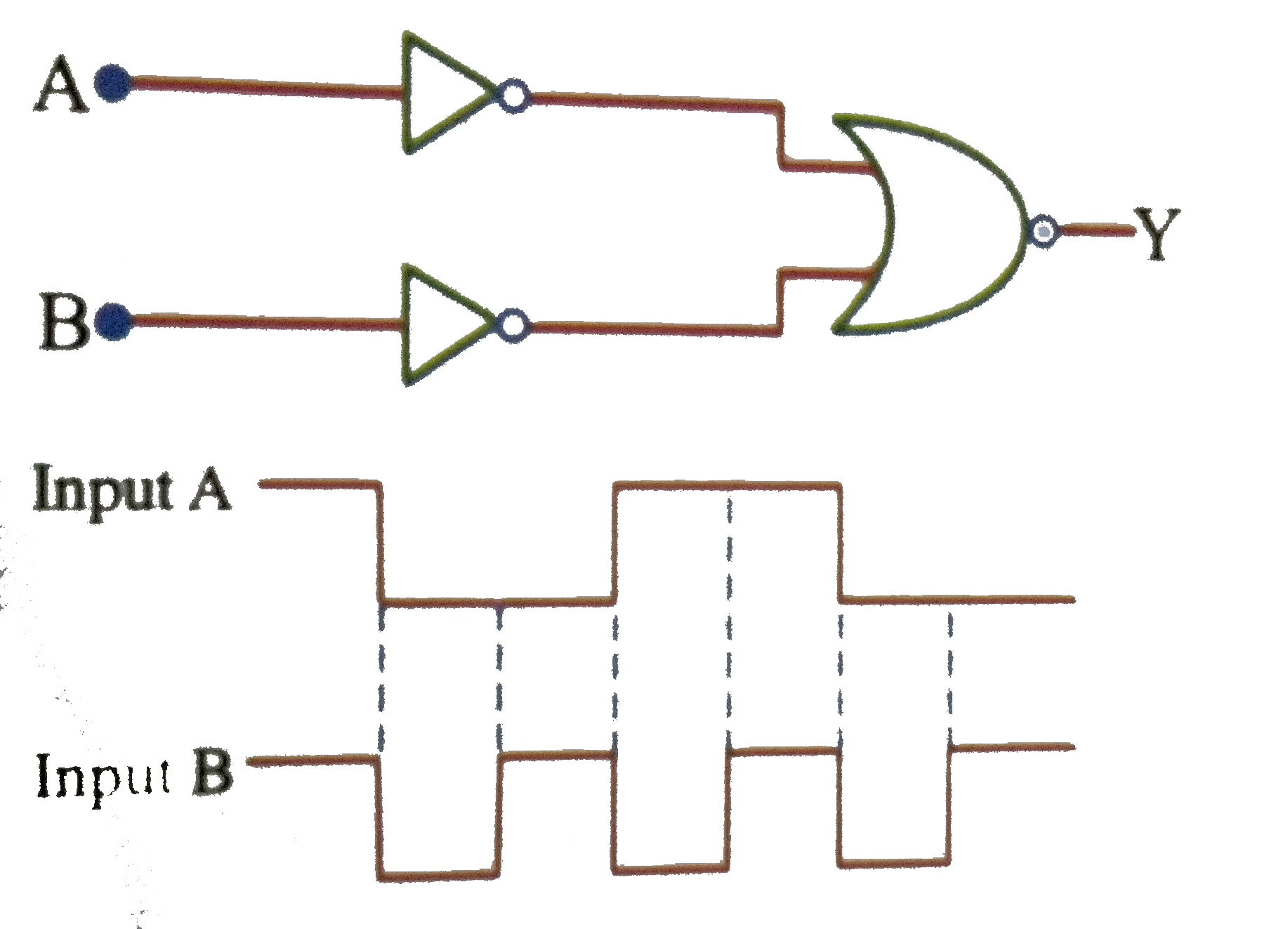
The logic circuit shown below has the input waveforems 'A' and 'B' as shown. Pick out the correct output waveform
A

B

C

D

Video Solution
Text Solution
The correct Answer is:A

The output of the circuit is
=Y=¯¯¯¯¯¯¯¯¯¯¯¯¯¯¯A+¯¯¯B=¯¯¯¯¯¯¯A.¯¯¯¯¯¯B=A.B (By de Morgan's theorem)
It is the Boolean expression of AND gate.
The output waveform corresponding to given input waveforms A and B is as shown below

|
Topper's Solved these Questions
- SEMICONDUCTOR ELECTRONICS : MATERIALS , DEVICES AND SIMPLE CIRCUITS BOOK - NCERT FINGERTPS ENGLISHCHAPTER - SEMICONDUCTOR ELECTRONICS : MATERIALS , DEVICES AND SIMPLE CIRCUITS EXERCISE - HOTS
8 Videos
- SEMICONDUCTOR ELECTRONICS : MATERIALS , DEVICES AND SIMPLE CIRCUITS BOOK - NCERT FINGERTPS ENGLISHCHAPTER - SEMICONDUCTOR ELECTRONICS : MATERIALS , DEVICES AND SIMPLE CIRCUITS EXERCISE - NCERT
8 Videos
- RAY OPTICS AND OPTICAL INSTRUMENTSBOOK - NCERT FINGERTPS ENGLISHCHAPTER - RAY OPTICS AND OPTICAL INSTRUMENTSEXERCISE - NCERT Exemplar
11 Videos
- WAVE OPTICSBOOK - NCERT FINGERTPS ENGLISHCHAPTER - WAVE OPTICSEXERCISE - Assertion And Reason
15 Videos
Similar Questions
Knowledge Check
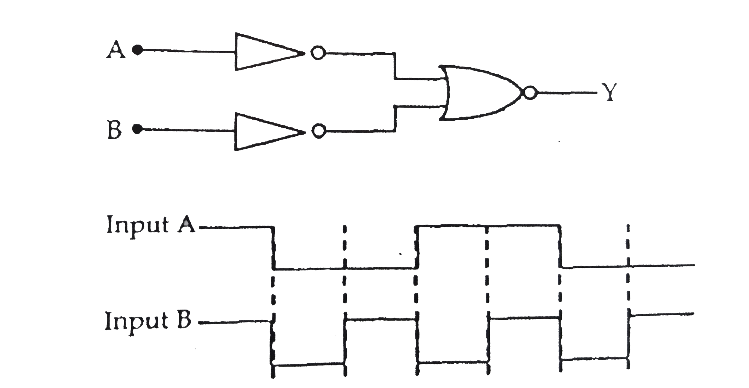
The logic circuit shown below has the input waveforems 'A' and 'B' as shown. Pick out the correct output waveform
 A
A B
B C
C D
D
A circuit is shown below.
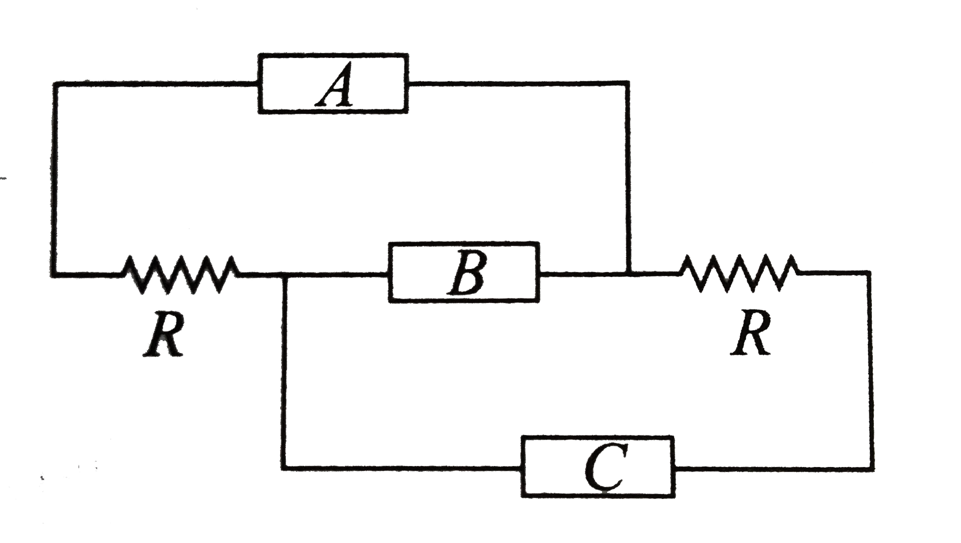
View SolutionFor the logic circuit shown the truth table is

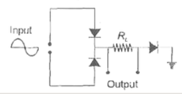
View SolutionIn the circuit shown , the input waveform is given. Which of the following correctly gives the output wavefrorm across RL?
View SolutionThe current l in the circuit shown below is
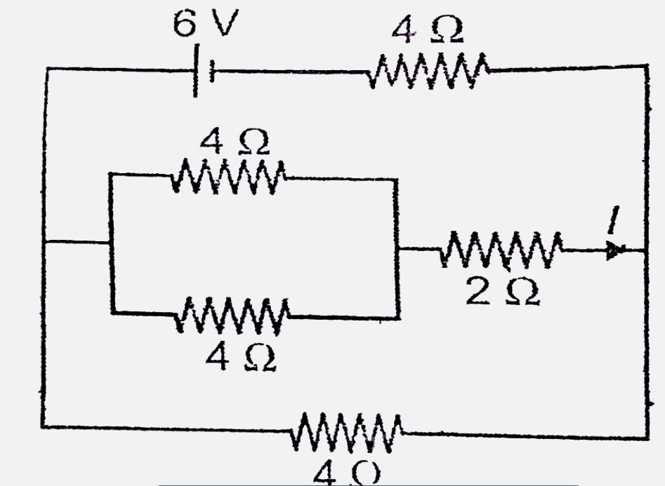
View SolutionIn the circuit shown below, V should be:
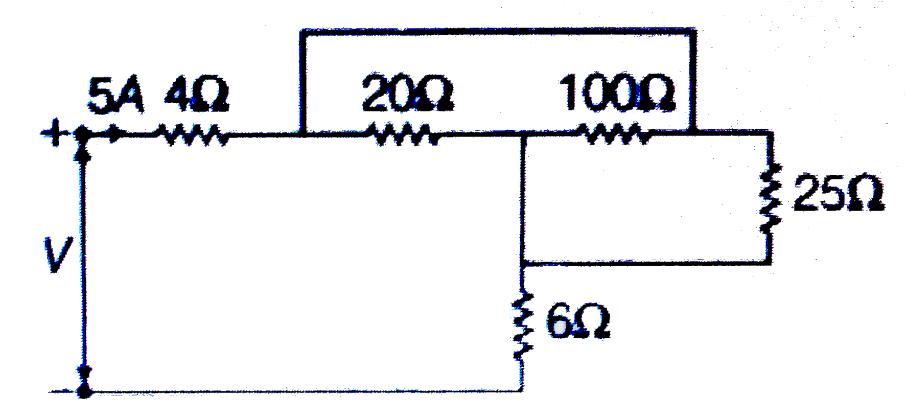
View SolutionIn the given circuit as shown the two input waveform A and B are applied simultaneously. The resultant waveform Y is
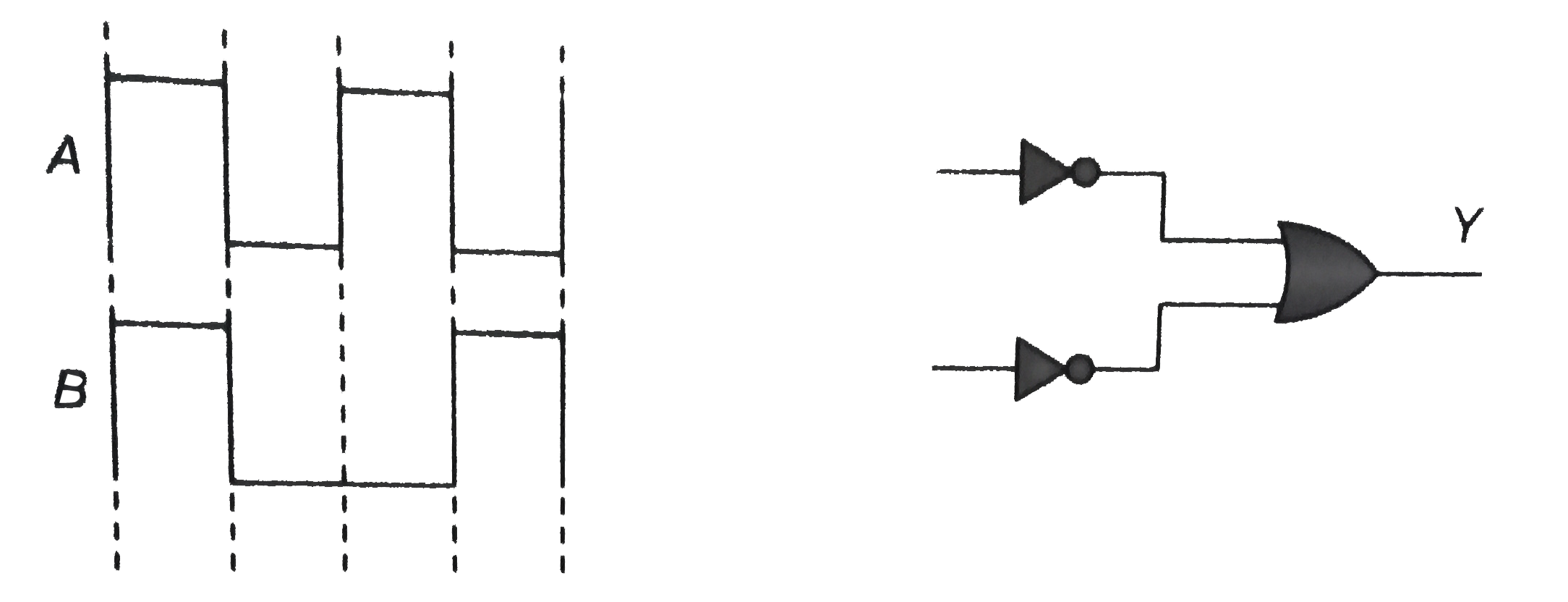
View SolutionThe current I in the circuit shown below is
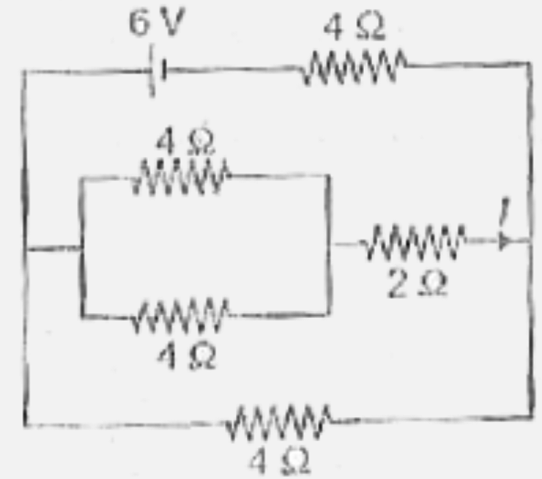
View Solution

 .
.