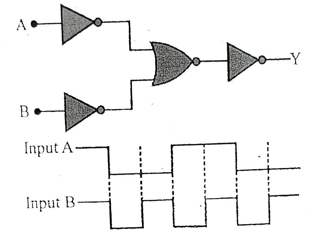
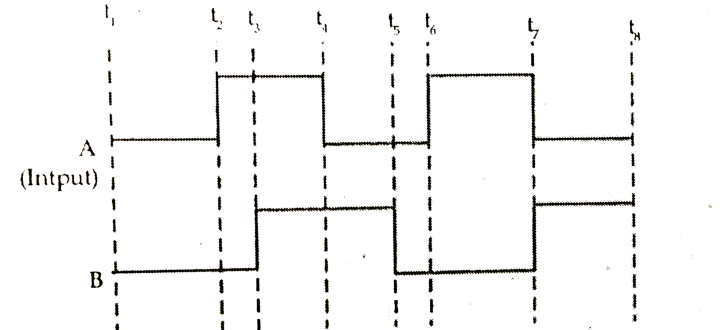
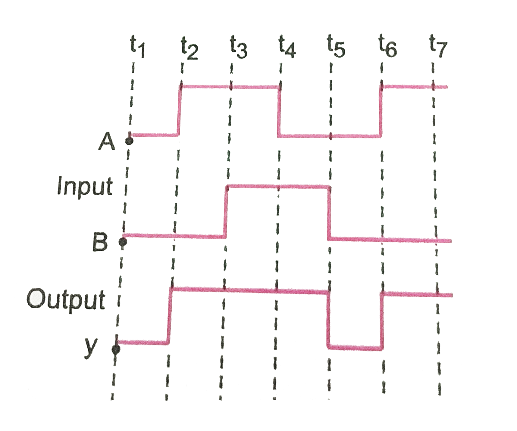
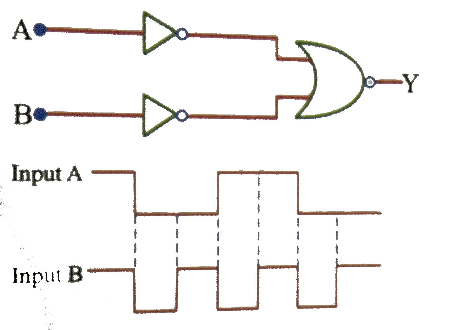
The logic circuit shown has the input waveforms 'A' and 'B' as shown. Pick out the CORRECT output waveform:-


The correct Answer is:A
Output equation y=¯¯¯A+¯¯¯B=¯¯¯A.¯¯¯B
Topper's Solved these Questions
- TEST PAPERSBOOK - ALLENCHAPTER - TEST PAPERSEXERCISE - Part-1 Physics
15 Videos
- TEST PAPERSBOOK - ALLENCHAPTER - TEST PAPERSEXERCISE - part-2 physics
71 Videos
- TEST PAPERSBOOK - ALLENCHAPTER - TEST PAPERSEXERCISE - PAPER 2
60 Videos
- TEST PAPER 4BOOK - ALLENCHAPTER - TEST PAPER 4EXERCISE - PHYSICS
44 Videos
- UNIT & DIMENSIONS, BASIC MATHS AND VECTOR BOOK - ALLENCHAPTER - UNIT & DIMENSIONS, BASIC MATHS AND VECTOR EXERCISE - Exercise (J-A)
7 Videos
Similar Questions
Knowledge Check
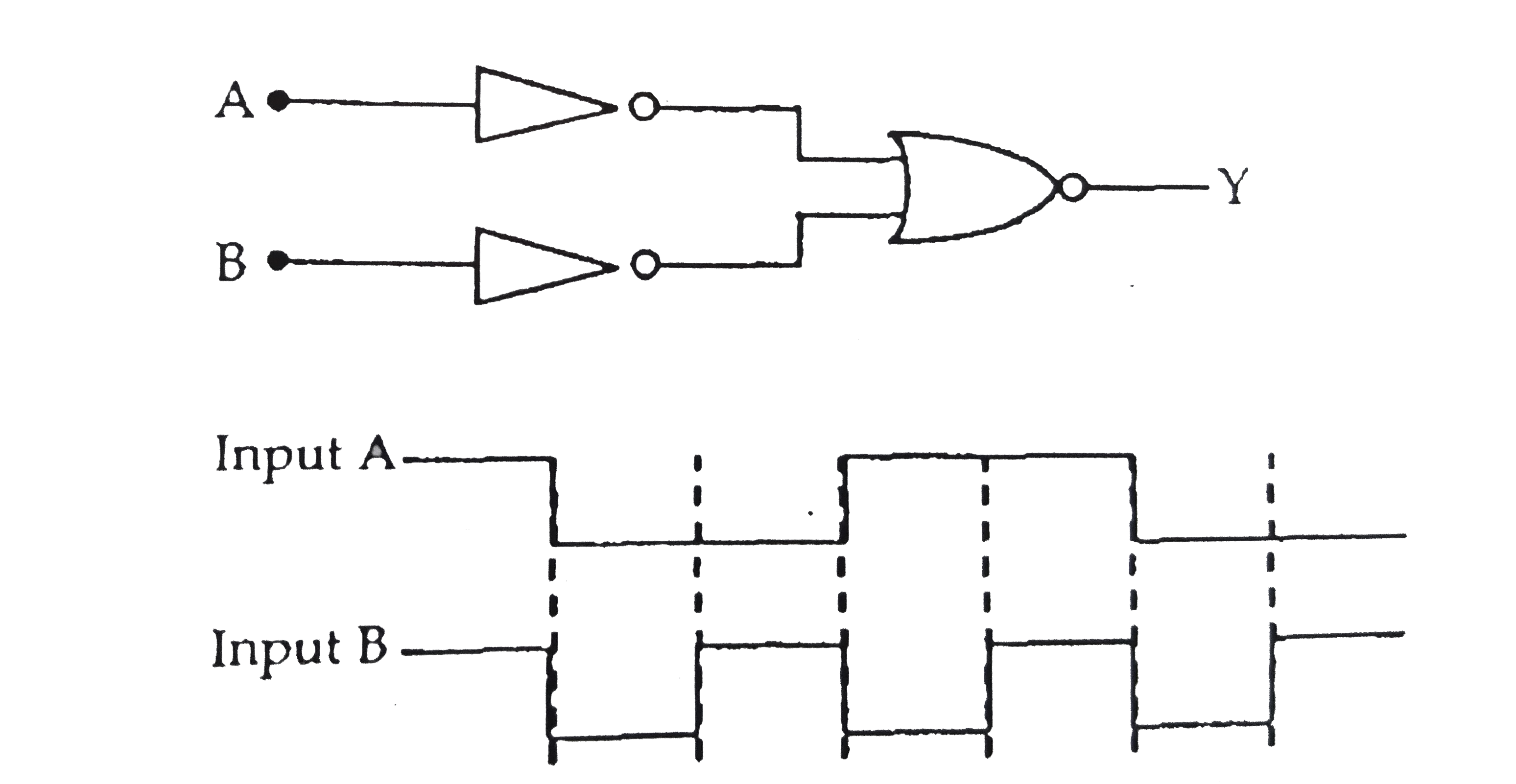
The logic circuit shown below has the input waveforems 'A' and 'B' as shown. Pick out the correct output waveform
 A
A B
B C
C D
D
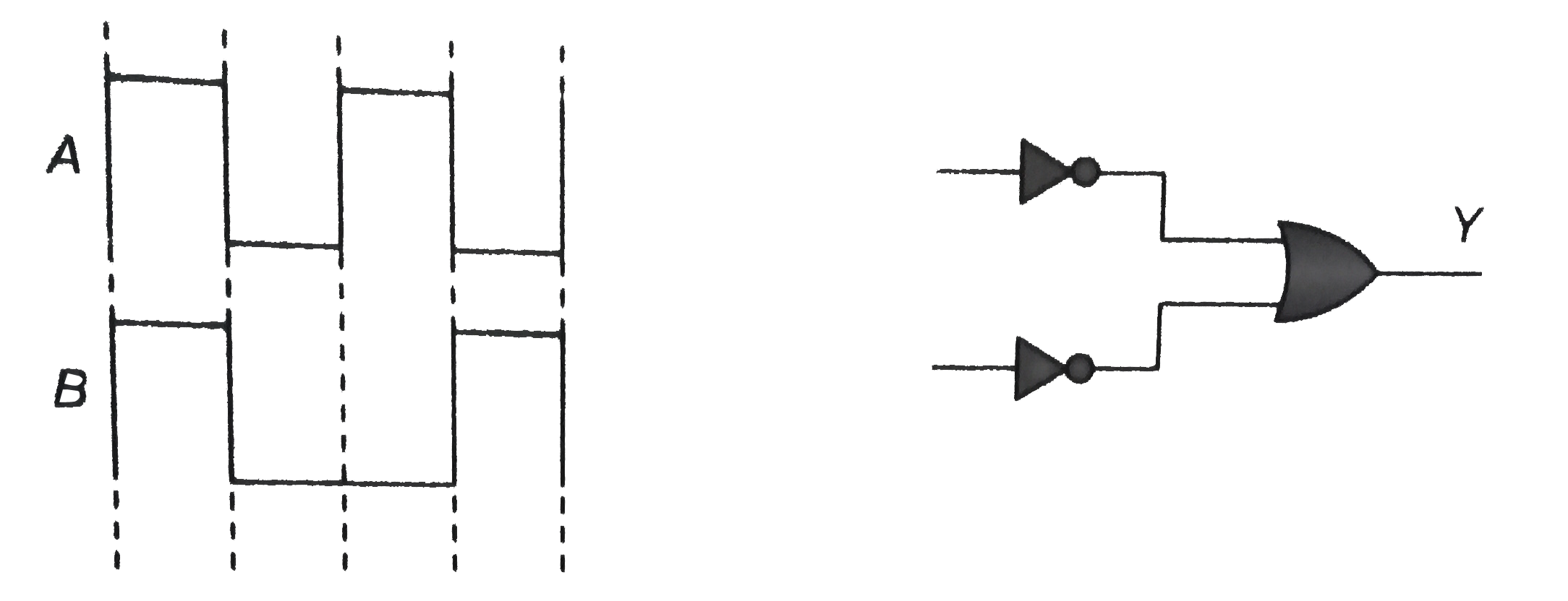
In the given circuit as shown the two input waveform A and B are applied simultaneously. The resultant waveform Y is
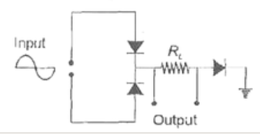
View SolutionIn the circuit shown , the input waveform is given. Which of the following correctly gives the output wavefrorm across RL?
View Solution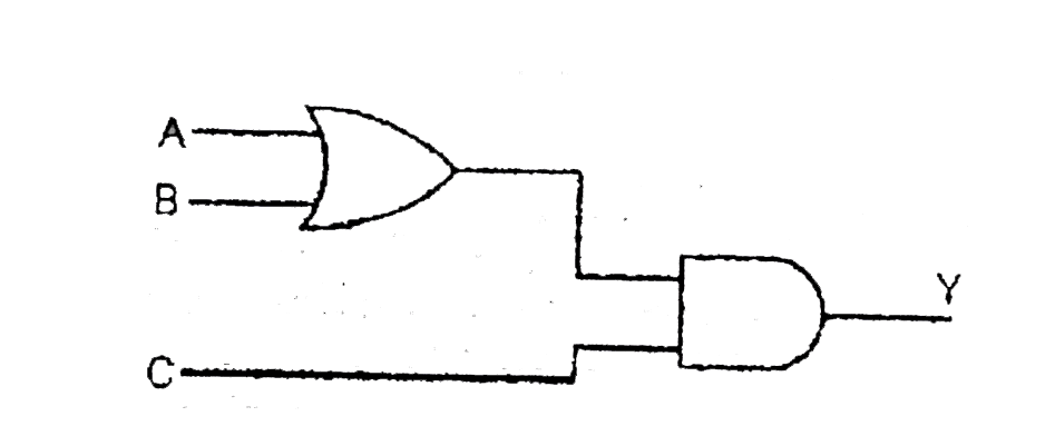
For the logic circuit shown the boolean relation is-
View SolutionThe figure shows the input weveforms A and B for 'AND' gate Draw the output waveform and write the truth table for this logic gate
 .
.
View SolutionThe Fig shown input waveforms A and B to a logic gate. Draw the output waveform for an OR gate. Write the truth table for this logic gate and draw its logic symbol.
View SolutionThe following Fig. shows the input waveforms (A,B) and the output waveform (y) of a gate. Identify the gate and write its truth table.
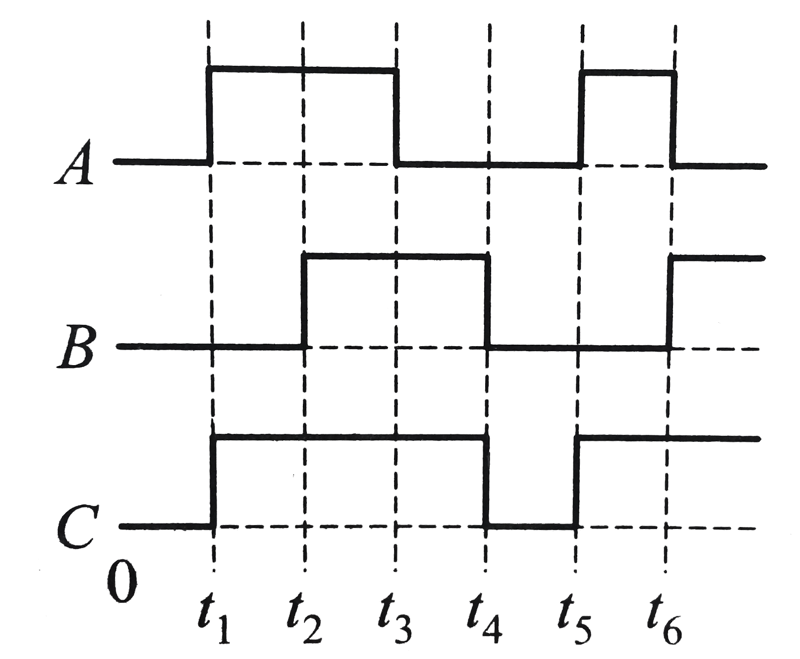
View SolutionThe figure shows a logic circuit with two inputs A and B and the output C. The voltage wave forms across A,B and C are as given. The logic circuit gate is
View Solution

 .
.