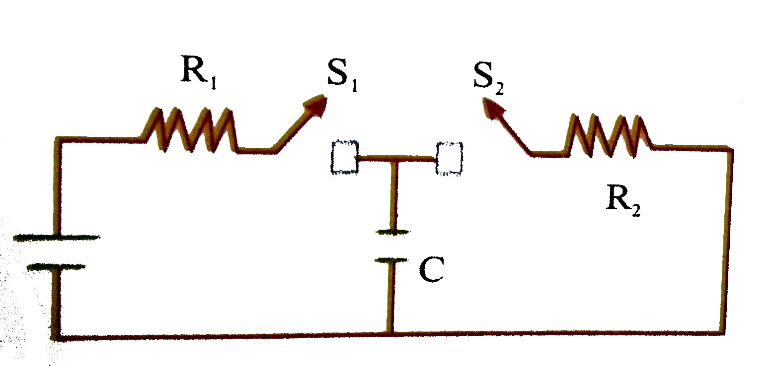
A battery of emf V volts, resistances R1 and R2, a condenser C and switches S1, and S2, are connected in a circuit as shown. The capacitor C gets fully charged to V volts when
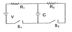
S1 and S2 are both closed
S1 and S2 are both open
S1 closed and S2 is open
S1 is closed and S2 is open
The correct Answer is:C
Step by step video, text & image solution for A battery of emf V volts, resistances R_(1) and R_(2), a condenser C and switches S1, and S2, are connected in a circuit as shown. The capacitor C gets fully charged to V volts when by Physics experts to help you in doubts & scoring excellent marks in Class 12 exams.
Updated on:21/07/2023Topper's Solved these Questions
- CURRENT ELECTRICITYBook:FIITJEEChapter:CURRENT ELECTRICITYExercise:ASSIGNMENT PROBLEMS (OBJECTIVE)(Level-II)
Explore 20 Videos
- CURRENT ELECTRICITYBook:FIITJEEChapter:CURRENT ELECTRICITYExercise:Comprehension -(1)
Explore 5 Videos
- CURRENT ELECTRICITYBook:FIITJEEChapter:CURRENT ELECTRICITYExercise:ASSIGNMENT PROBLEMS (SUBJECTIVE)(Level-II//III)
Explore 14 Videos
- COLLISION Book:FIITJEEChapter:COLLISION Exercise:(NUMERICAL BASED QUESTIONS)
Explore 4 Videos
- ELASTICITY AND WAVES Book:FIITJEEChapter:ELASTICITY AND WAVES Exercise:Assignment Problems (Objective) Level-II
Explore 15 Videos
Similar Questions
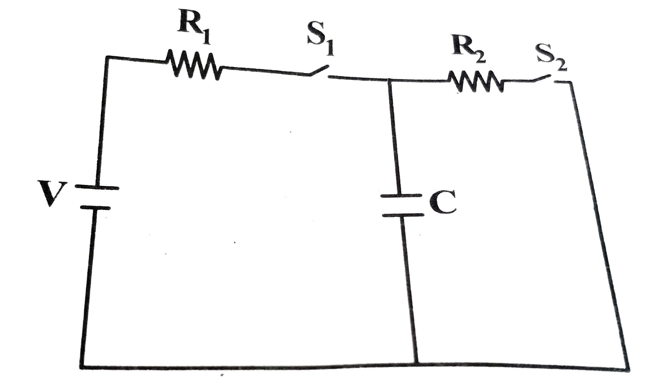
In the circuit shown above, when do the condenser (C) get fully charged to volts ?
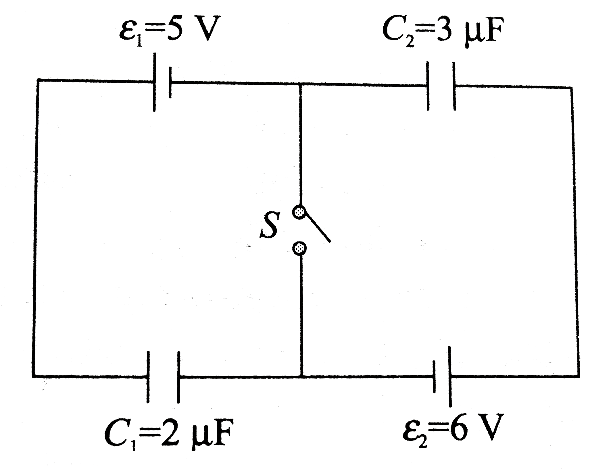
View SolutionTwo capacitors C1andC2 are connected with two batteries of emf ε1 and ε2. The circuit components are connected with a switch S as shown in. Initially the switch is open and the capacitors are charged. Find the heat produced when switch S is closed.
 .
.
View Solution
Knowledge Check
A battery of emf V volts, resistances R1 and R2, a condenser C and switches S1, and S2, are connected in a circuit as shown. The capacitor C gets fully charged to V volts when
 AS1 and S2 are both closedBS1 and S2 are both openCS1 is open and S2 is closedDS1 is closed and S2 is open
Two batteries of emf E1 and E2, a capacitor of capacitance I 'C' and a resistor R are connected in a circuit as shown When the switch S is shifted from position (1) to (2), then Esta the charge flow and work done by battery E2
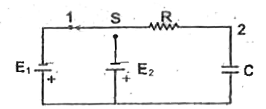 A△q=C(E2−E1)Btr∈g≤W=C(E2−E1)E2C△q=C(E2−E1)D△W=q222C−q212C
In the circuit, a battery of emf E, a resistance R and inductance coil L1andL2 and switch S are connected as shown. In Fig. Initially the switch is open
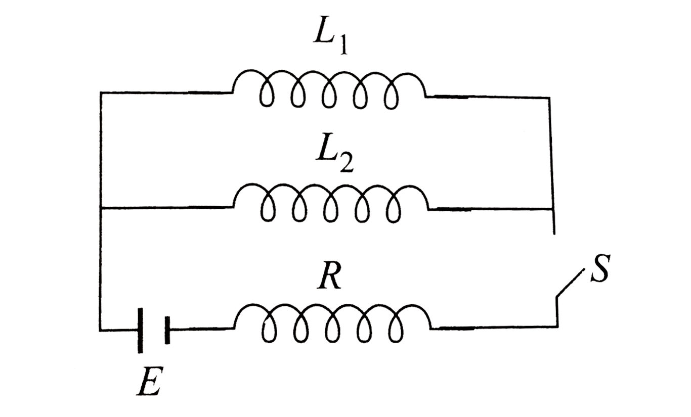 AThe time constant of the circuit is 1RL1L2L1+L2BSteady state current in the inductor L1is(EL_(2))/(R(L_(1)+L_(2)))CSteady state current in the inductor L2 is EL1R(L1+L2)DIn steady the total energy stored in the inductor coils is 12L1L2L1+L2E2R2
The circuit consists of two resistors (of resistance R1=20Ω and R2=10Ω), a capacitor (of capacitance C=10μF) and two ideal cells. In the circuit shown the capacitor is in steady state and the switch S is open
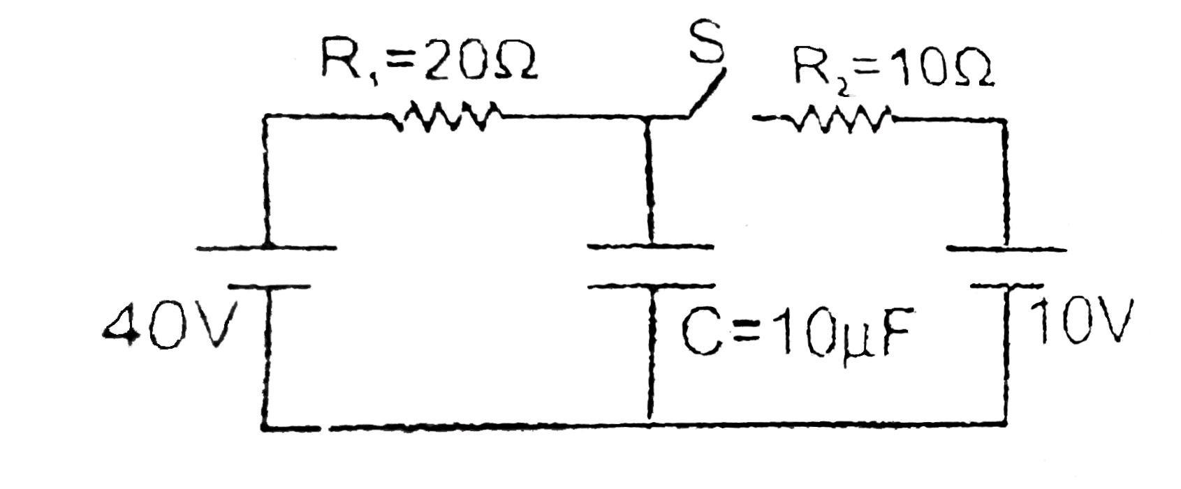
The charge on capacitor in steady state with switch S closed.
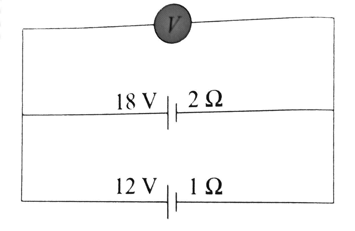
View SolutionTwo batteries, one of emf 18 volts and internal resistance 2Ω and the other fo emf 12 volts and internal resistance 1Ω, are connected as shown. The voltmeter V will record a reading of
View SolutionThe circuit consists of two resistors (of resistance R1=20Ω and R2=10Ω), a capacitor (of capacitance C=10μF) and two ideal cells. In the circuit shown the capacitor is in steady state and the switch S is open
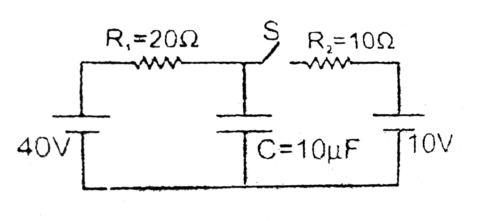
The current through the resistor R2 just after the switch S is closed is :
View SolutionA capacitor C is connected to a battery circuit having two switches S1 and S2 and resistances R1 and R2. The capacitor will be fully charged when
 .
.
View SolutionIn the given circuit the capacitor (C) may be charged through resistance R by a battery V by closing switch (S1). Also when (S1) is opend and (S2) is closed the capacitor is connected in series with inductor (L).
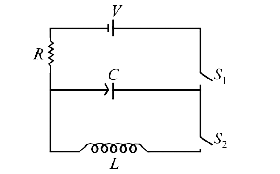
When the capacitor gets charged compleely, (=(S1) is opened and (S2) is closed, Then,
View Solution

