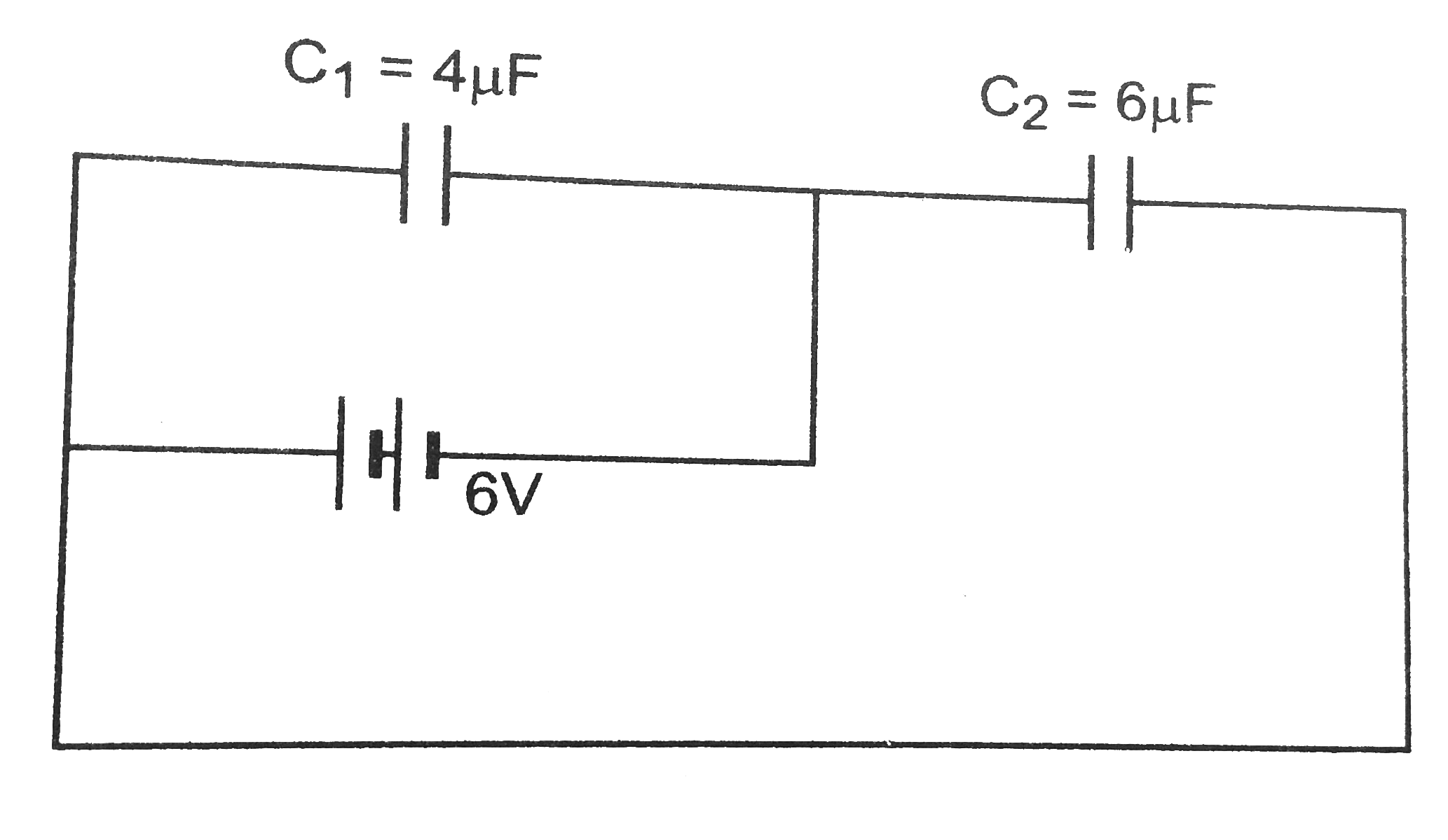
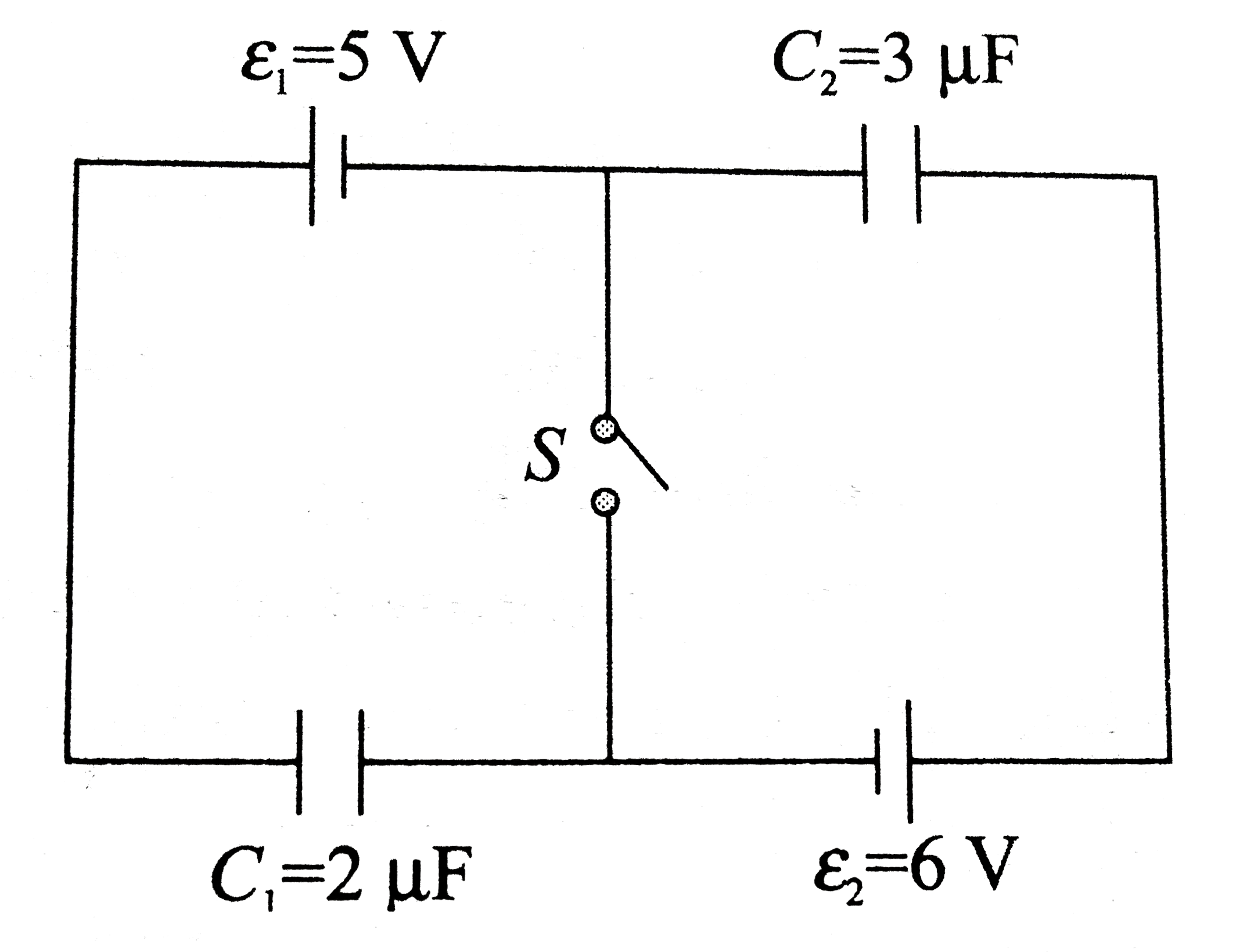
Two capacitors C1andC2 are connected with two batteries of emf ε1 and ε2. The circuit components are connected with a switch S as shown in. Initially the switch is open and the capacitors are charged. Find the heat produced when switch S is closed.
 .
.
The correct Answer is:40μJ
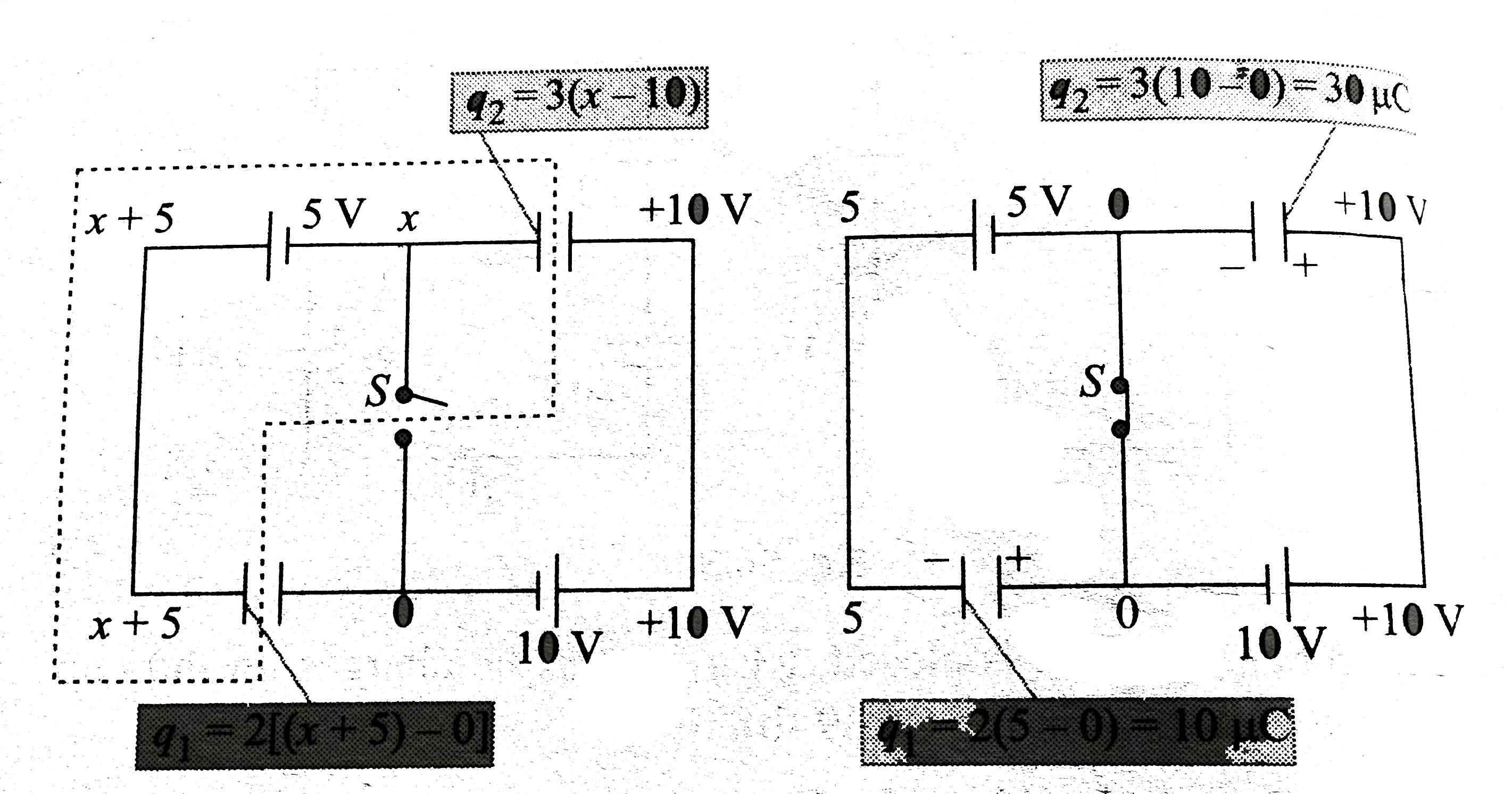
When switch id opened, let us consider consider an isolated system as shown. In this isolated system, net charge should be zero.
3(x−10)+2(x+5)2=0 or x=4
Hence charge on C1 is q1=2(4+5)=18μC
And charge on C2 is q2=3(4−10)=−18μC, or left plate is negative.
Hence, charge on C2 is q2=18μC (right plate is positive )
 .
.
When switch is closed, the final charge is should in the figure. Note that Δq1=8μC is charging battery, hence work done by 5V battery will be negative.
W5V=−(8μC)(5V)=−40μJ
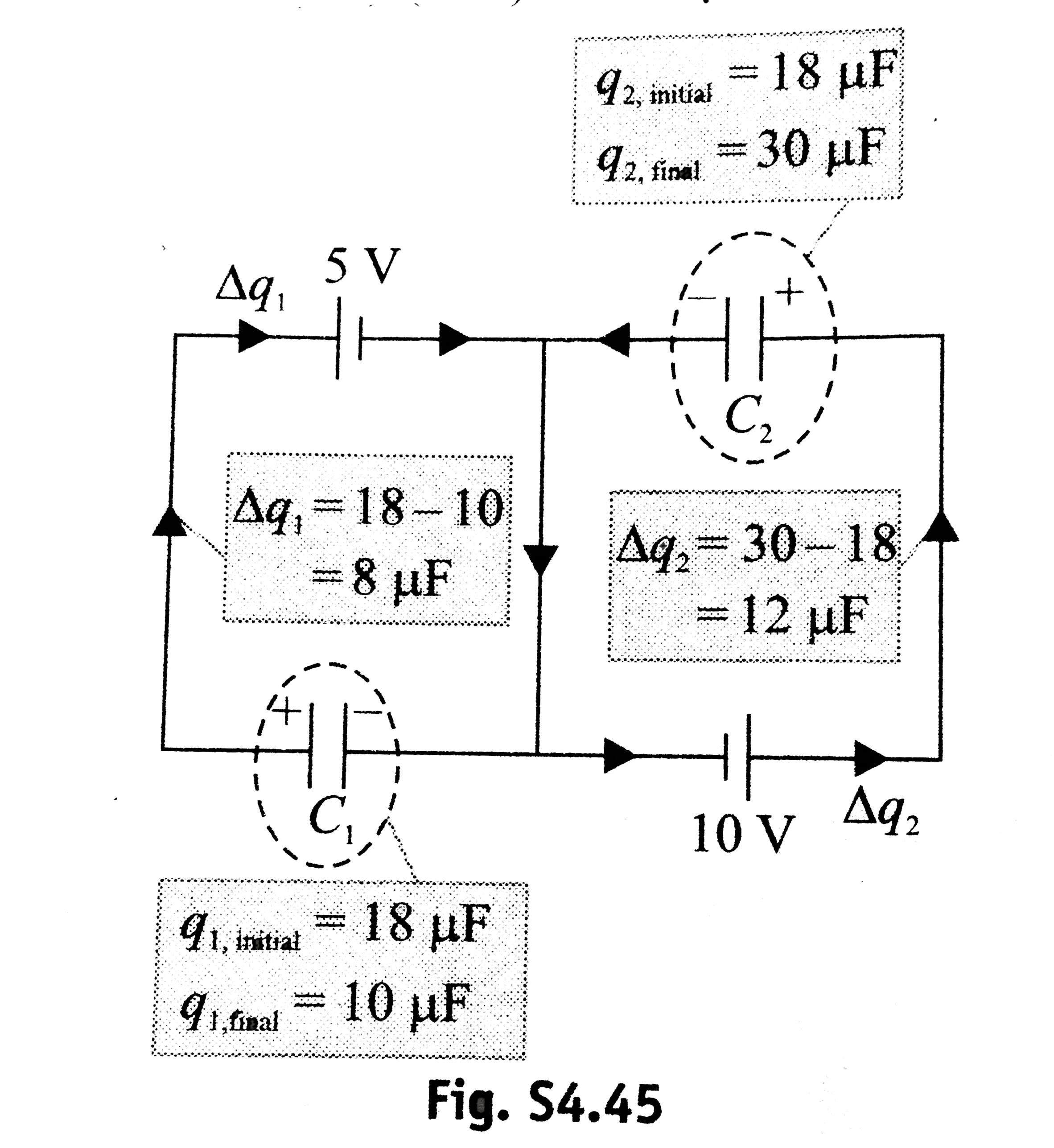
Δq2 is moving from positive terminal of 10V battery Net work done by batteries is work done by 10V battery is (120μC)(10V)=120μJ.
Net work done batteries is
Wbattery=−40+120=80μJ
Change in potential energy of the capacitors
ΔU=Uf−Ui
=(123[10]2+122[5]2)−(123[6]2+12[9]2)=40μJ.
Topper's Solved these Questions
- CAPACITOR AND CAPACITANCEBook:CENGAGE PHYSICSChapter:CAPACITOR AND CAPACITANCEExercise:Single Correct
Explore 49 Videos
- CAPACITOR AND CAPACITANCEBook:CENGAGE PHYSICSChapter:CAPACITOR AND CAPACITANCEExercise:Multile Correct
Explore 11 Videos
- CAPACITOR AND CAPACITANCEBook:CENGAGE PHYSICSChapter:CAPACITOR AND CAPACITANCEExercise:Exercise 4.2
Explore 32 Videos
- ATOMSBook:CENGAGE PHYSICSChapter:ATOMSExercise:QUESTION BANK
Explore 40 Videos
- CENGAGE PHYSICS DPPBook:CENGAGE PHYSICSChapter:CENGAGE PHYSICS DPPExercise:subjective type
Explore 51 Videos
Similar Questions
Knowledge Check
In the circuit, a battery of emf E, a resistance R and inductance coil L1andL2 and switch S are connected as shown. In Fig. Initially the switch is open
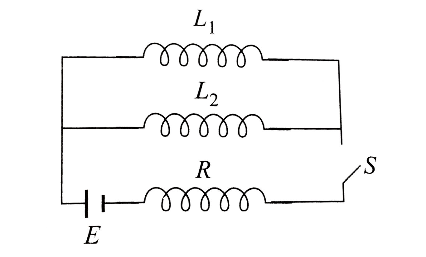 AThe time constant of the circuit is 1RL1L2L1+L2BSteady state current in the inductor L1is(EL_(2))/(R(L_(1)+L_(2)))CSteady state current in the inductor L2 is EL1R(L1+L2)DIn steady the total energy stored in the inductor coils is 12L1L2L1+L2E2R2
Two capacitors A and B are connected in series with a battery as shown in the figure. When the switch S is closed and the two capacitors get charged fully, then
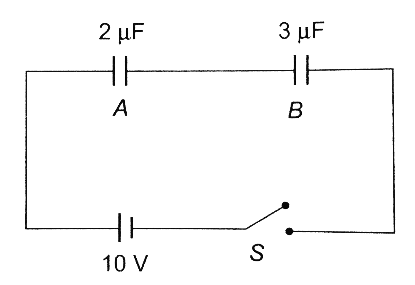 AThe potential difference across the plates of A is 4V and across the plates of B is 6VBThe potential difference across the plates of A is 6V and across the plates of B is 4VCThe ratio of electrical energies stored in A and B is 2:3DThe ratio of charges on A and B is 3:2
Two capacitor C1 and C2, charged with chargesq1 and q2 then these are connected in series with an uncharged capacitor C, as shown in figure. As the switch S is closed :
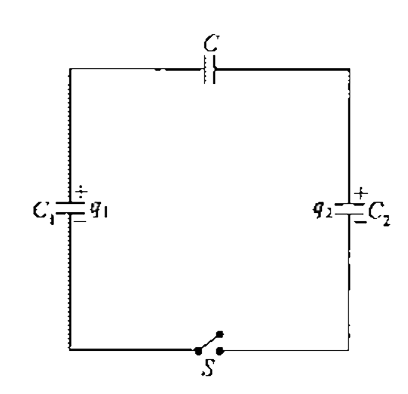 AC gets charged in any conditionBC gets charged only when q1C2>q2C1CC gets charged only when q1C2<q2C1DC gets chharged when q1C2≠q2C1
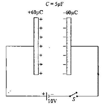
A capacitor of 5μF capacitance is charged with an initial charge 60μC as shown in figure and connected across a 10Vbattery. Find the amount of heat produced when switch is closed.
View SolutionConsider the situation shown in figure (31-E23 ) . The switch S is open for a long time and then closed . (a) Find the charge flown through the battery when the switch S is closed (b)Find the done by the battery .

View SolutionFind heat produced in the capacitors after long time on closing the switch S
View SolutionIn the circuit shown in the figure, the capacitor C is charged to a potential Vo. The heat generated in the circuit when the switch S is closed, is
View SolutionIn the circuit shown each capacitor has a capcitance C. The emf of the celll is E. If the switch S is closed then
View Solution


