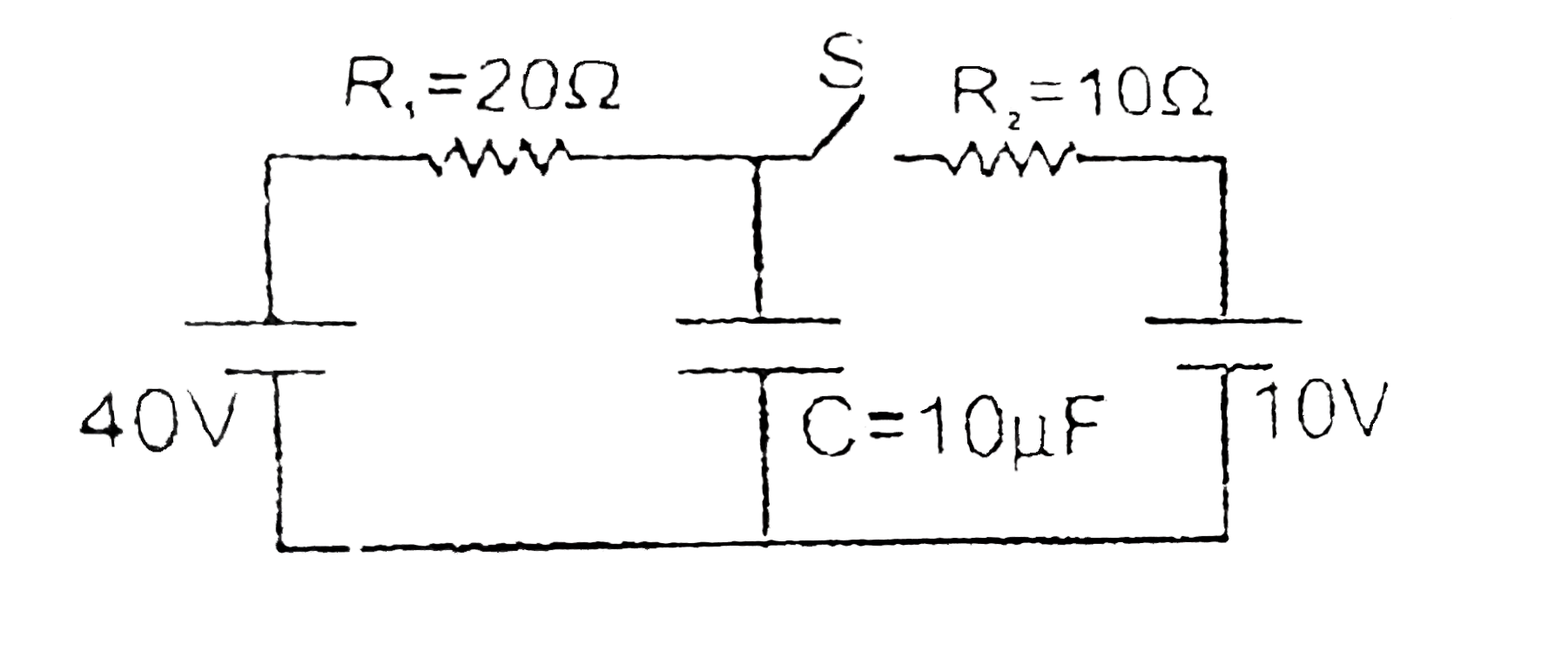
The circuit consists of two resistors (of resistance R1=20Ω and R2=10Ω), a capacitor (of capacitance C=10μF) and two ideal cells. In the circuit shown the capacitor is in steady state and the switch S is open
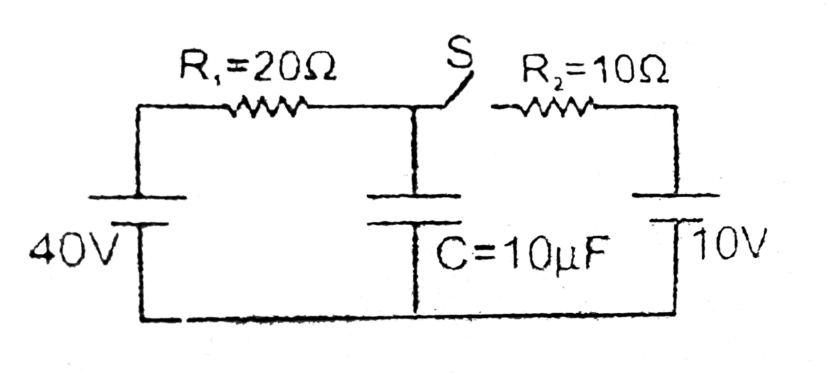
The current through the resistor R2 just after the switch S is closed is :
1 ampere
2 ampere
3 ampere
4 ampere
The correct Answer is:C
In steady statem before the switch S is closed, potential difference across capacitor is 40 volts. Just after switch S is closed, charge and hence potential difference across the capacitor does not change apreciably. So, the potential difference across R2 is 40−10=30 volt. The current through R2 is 3 ampere.
Topper's Solved these Questions
- DAILY PRACTICE PROBLEMBook:RESONANCEChapter:DAILY PRACTICE PROBLEMExercise:DPP No.49
Explore 20 Videos
- DAILY PRACTICE PROBLEMBook:RESONANCEChapter:DAILY PRACTICE PROBLEMExercise:DPP No.50
Explore 9 Videos
- DAILY PRACTICE PROBLEMBook:RESONANCEChapter:DAILY PRACTICE PROBLEMExercise:DPP No.47
Explore 20 Videos
- CURRENT ELECTRICITYBook:RESONANCEChapter:CURRENT ELECTRICITYExercise:High Level Problems (HIP)
Explore 21 Videos
- ELECTRO MAGNETIC WAVESBook:RESONANCEChapter:ELECTRO MAGNETIC WAVESExercise:Exercise 3
Explore 27 Videos
Similar Questions
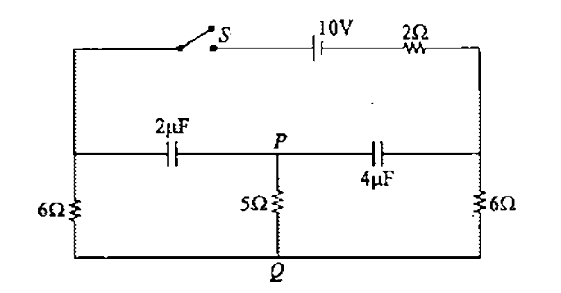
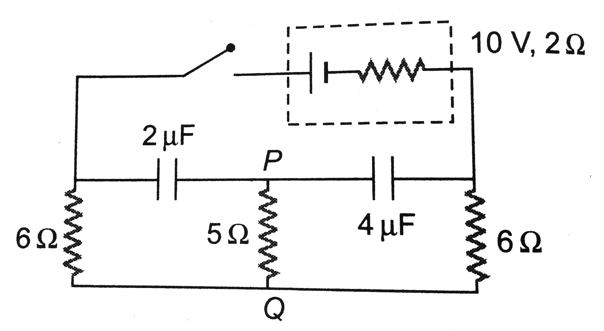
In the circuit shown in figure-3.351 the capacitors are initially uncharged. The current through resistor PQ just after closing the switch is :
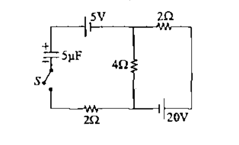
View SolutionIn the circuit shown in figure 3.242 capacitor is charged with 50μC charge. Find the current in 4Ω resistance just after switch S is closed.
View Solution
Knowledge Check
The circuit consists of two resistors (of resistance R1=20Ω and R2=10Ω), a capacitor (of capacitance C=10μF) and two ideal cells. In the circuit shown the capacitor is in steady state and the switch S is open
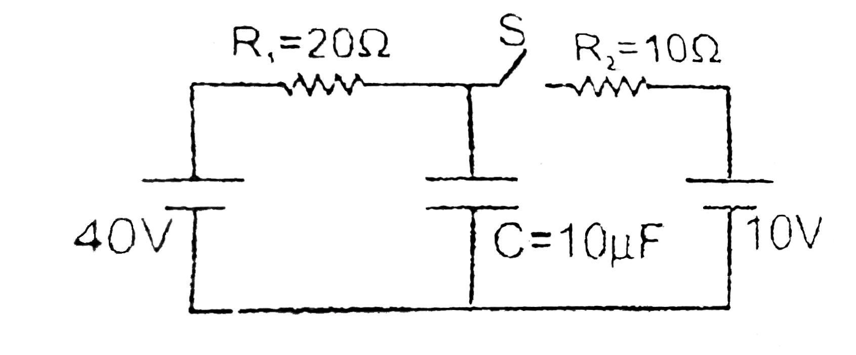
The charge on capacitor in steady state with switch S closed.A100μCB200μCC300μCD400μCThe circuit consists of two resistors (of resistance R1=20Ω and R2=10Ω), a capacitor (of capacitance C=10μF) and two ideal cells. In the circuit shown the capacitor is in steady state and the switch S is open
the circuit is in steady state with switch S closed. Now the switch S is opened. Just after the switch S is opened. the current through resistance R1 isA1 ampereB2 ampereC3 ampereD4 ampereIn the circuit shown in figure-3.348 when the switch is closed, the initial current through the 1Ω resistor just after closing the switch is
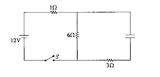 A2AB4AC3AD6A
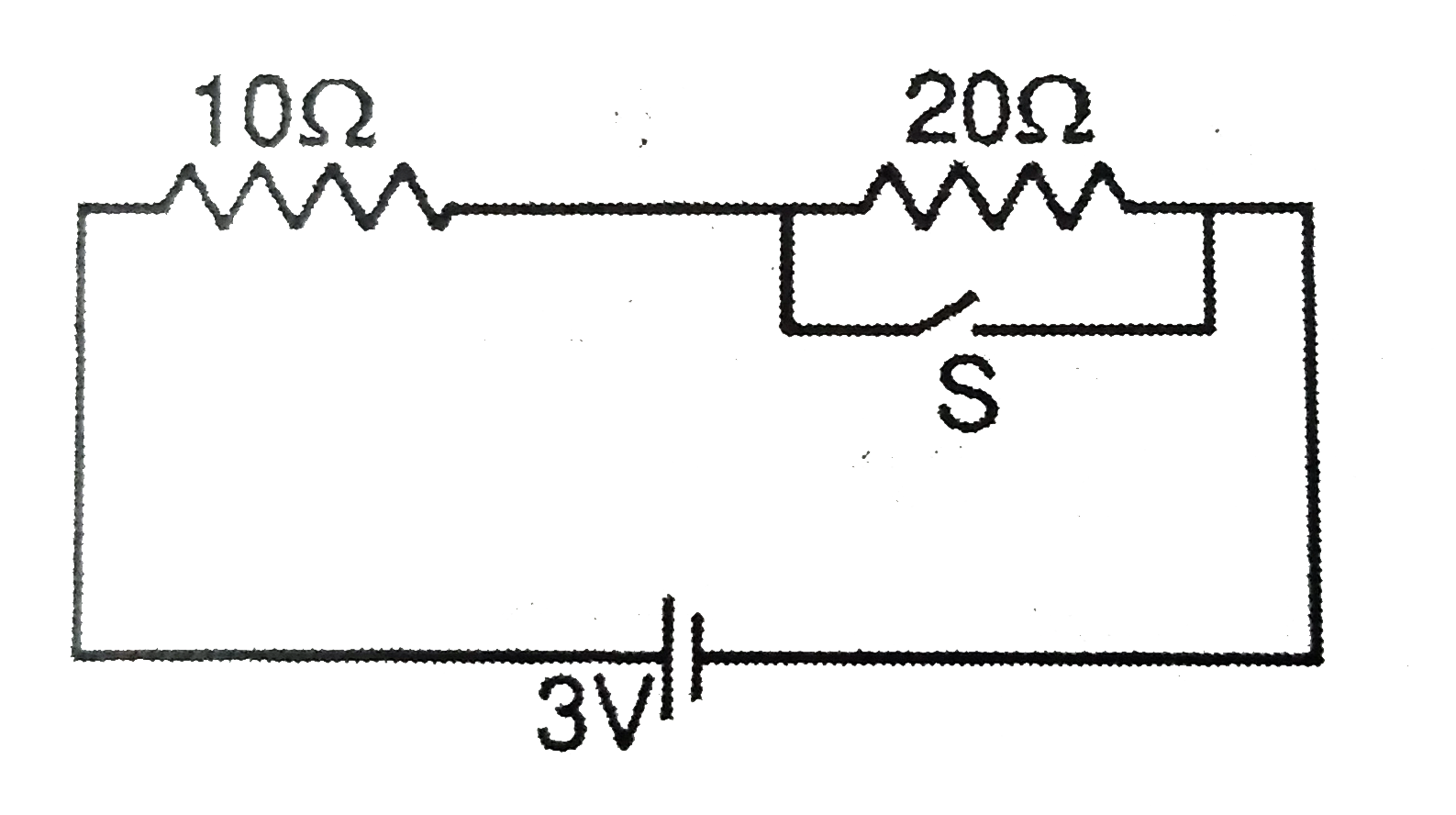
Consider the circuit shown in figure.Find the current through the10(Ω)resistor when the switch S is (a)open (b)closed .
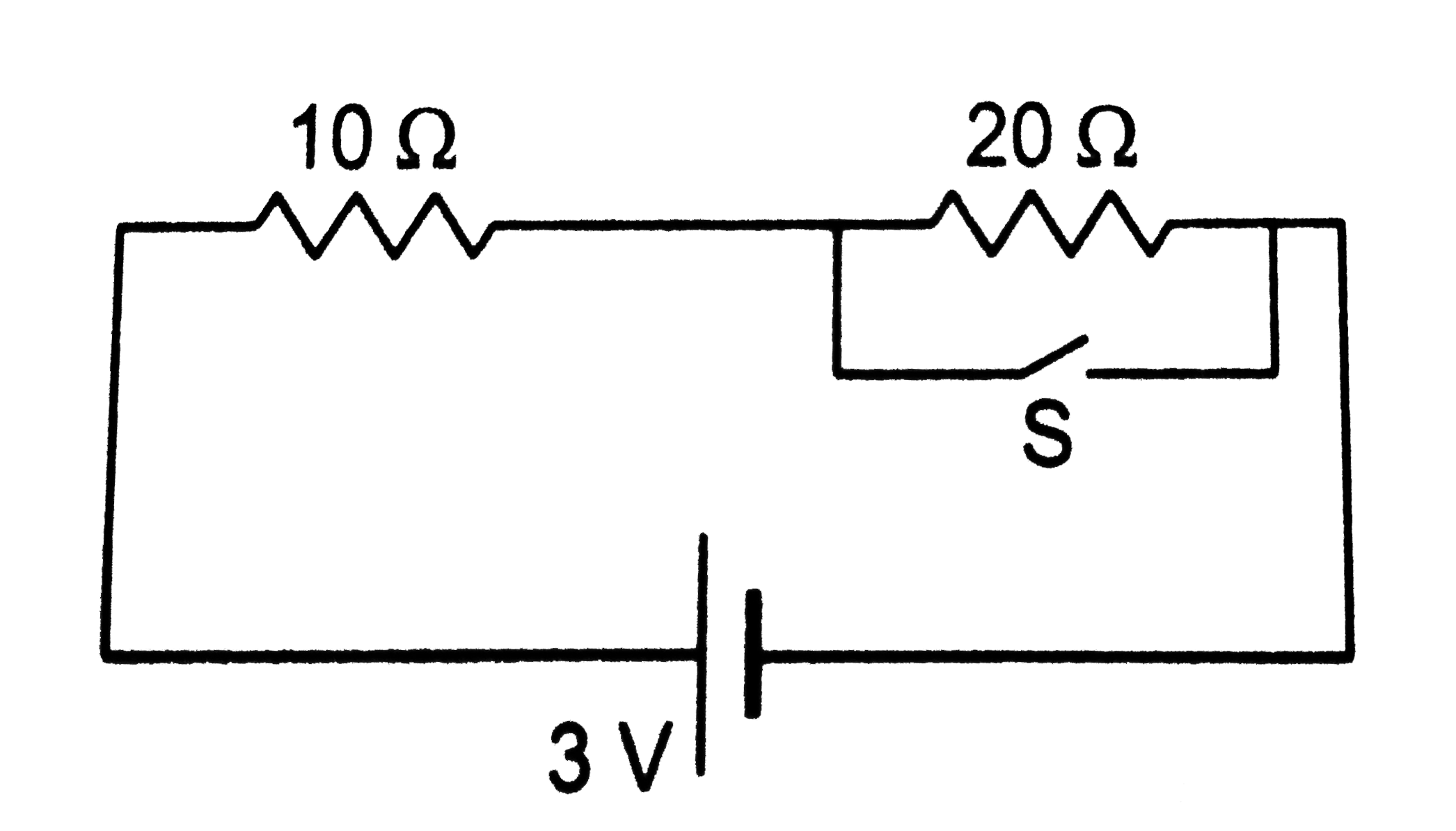
View SolutionConsider the circuit shown in figure. Find the current through the 10Ω resistor when the switch S is (a) opened (b) closed.
View SolutionIn the circuit shown in figure, the capacitors are initially uncharged. The current through resistor PQ just after closing the switch is
View Solution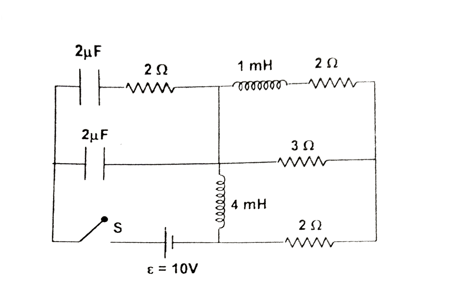
In the circuit shown, all the capacitors are initially uncharged. The current through the battery just after closing the switch 'S' is
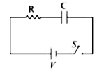
View SolutionIn the circuit shown, the capacitor is initially uncharged. The switch S is closed at t = 0. Time after which voltage across capacitor and resistor are equal is:
View Solution

