In the circuit shown, tp across the 2R resistor muhe voltage drost be
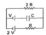
V
V2
4V3
2V3
The correct Answer is:C
Step by step video, text & image solution for In the circuit shown, tp across the 2R resistor muhe voltage drost be by Physics experts to help you in doubts & scoring excellent marks in Class 12 exams.
Updated on:21/07/2023Topper's Solved these Questions
- CURRENT ELECTRICITYBOOK - FIITJEECHAPTER - CURRENT ELECTRICITYEXERCISE - ASSIGNMENT PROBLEMS (OBJECTIVE)(Level-II)
20 Videos
- CURRENT ELECTRICITYBOOK - FIITJEECHAPTER - CURRENT ELECTRICITYEXERCISE - Comprehension -(1)
5 Videos
- CURRENT ELECTRICITYBOOK - FIITJEECHAPTER - CURRENT ELECTRICITYEXERCISE - ASSIGNMENT PROBLEMS (SUBJECTIVE)(Level-II//III)
14 Videos
- COLLISION BOOK - FIITJEECHAPTER - COLLISION EXERCISE - (NUMERICAL BASED QUESTIONS)
4 Videos
- ELASTICITY AND WAVES BOOK - FIITJEECHAPTER - ELASTICITY AND WAVES EXERCISE - Assignment Problems (Objective) Level-II
15 Videos
Similar Questions
In the circuit shown, the rms value of the voltage across the capacitor C, inductor L and resistor R1 are respectively 5√5V,10Vand5V.Thepeakvo<a≥(∈vo<)axrossR_(2) is
'(##CEN_KSR_PHY_JEE_C24_E01_018_Q08##)'
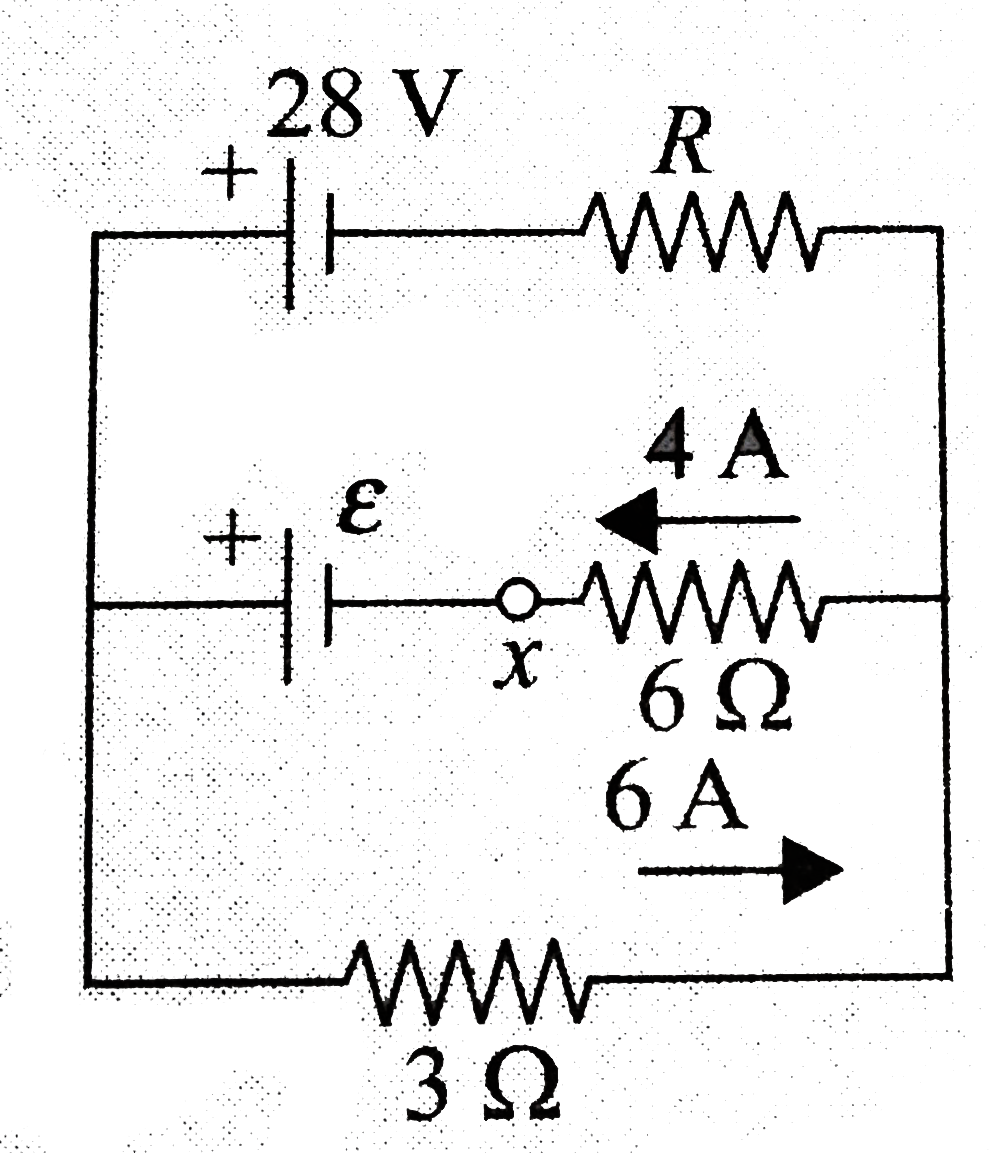
View SolutionIn the circuit shown in fig the voltage across the 2Ω resistor is 12V. What is the emf of the battery and the current thorugh the 6Oemga resistor?
View Solution
Knowledge Check
In the circuit shown, the voltage drop across the 15Ω resistor is 30V having the polarity as indicated. The ratio of potential difference across 5Ω resistor and resistance R is :
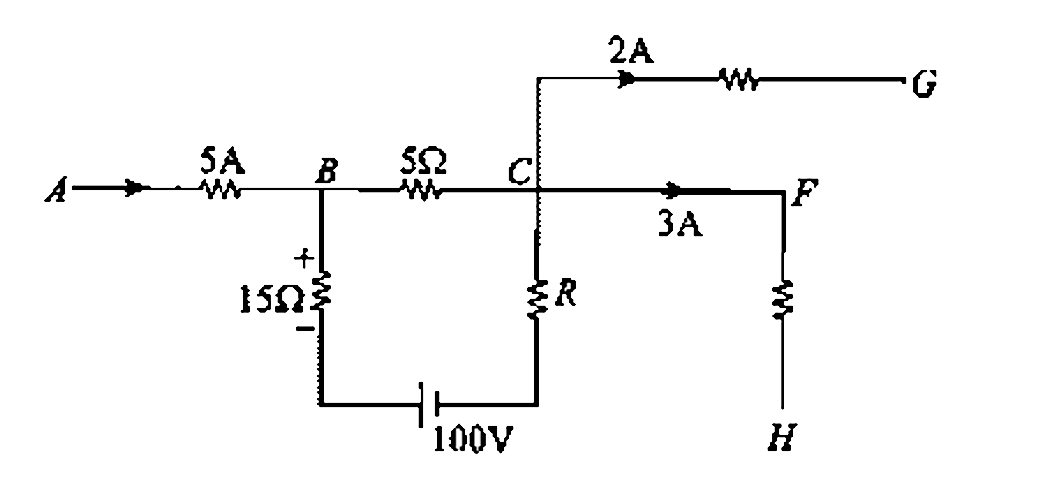 A2/7B0.4C5/7D1
In the circuit shown the voltage drop across the 15Ω resistor is 30V having the polarity as indicated. The ratio of potential difference across 5Ω and resistance R is
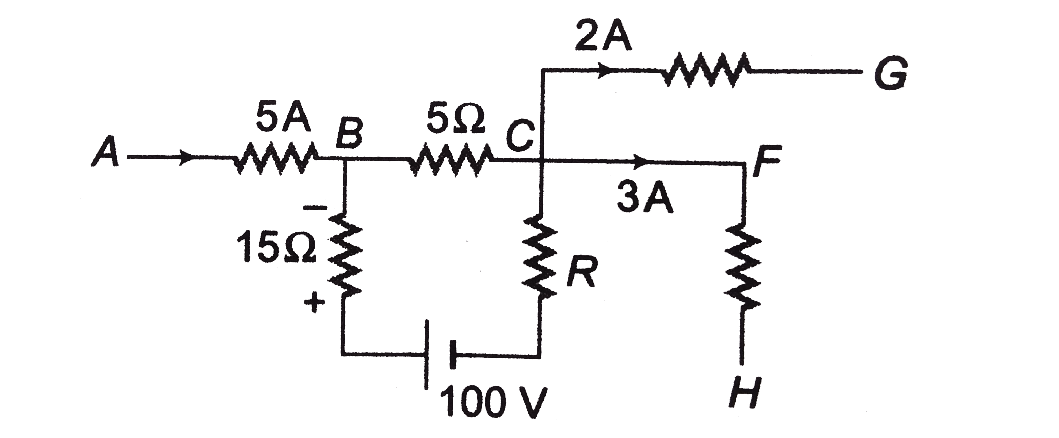 A2/7B0.4C5/7D1
For the circuit shown in the figure the rms value of voltage across R and coil are E1 and E2 respectively.
The power (thermal) developed across the coil is
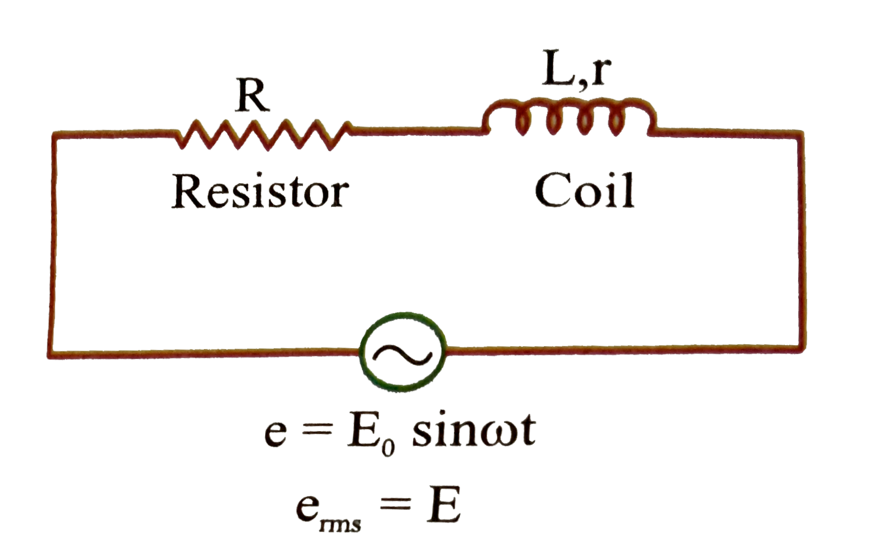 AE−E212RBE−E21−E222RCE22RD(E−E1)22R
A 1−kΩ resistor is connected in series with a 10−mH inductor, a 30V battery and an open switch. At time t=0, the switch is suddenly closed.
a. What is the maximum current in this circuit and when does it occur?
b. What are the voltage drops across the inductor and across the resistor 20μs after the switch is closed?
c. On a single set of axes, sketch the voltage across the resistor and the voltage across the inductor as functions of time. Also, sketch a graph of the current in the circuit as s function of time.
View SolutionIn the LCR circuit shown,if RMS voltages across resistor inductor and capacitor are equal,the RMS value of voltage across resistor will be
View SolutionUsing Kirchhoff's rules in the circuit shown determine (a) the voltage drop across the unknown resistor R, and (b) the current I in the arm EF.
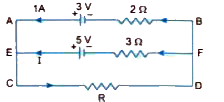
View SolutionFor the circuit shown in the figure , find the voltage across 10Ω resistor and the current passing through it .
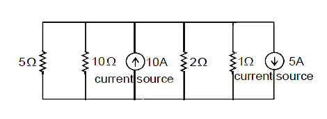
View SolutionIn the circuit shown in figure, the final voltage drop across the capacitor C is :
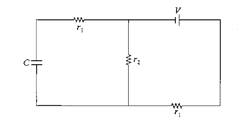
View Solution
