In the circuit shown in figure, the final voltage drop across the capacitor C is :
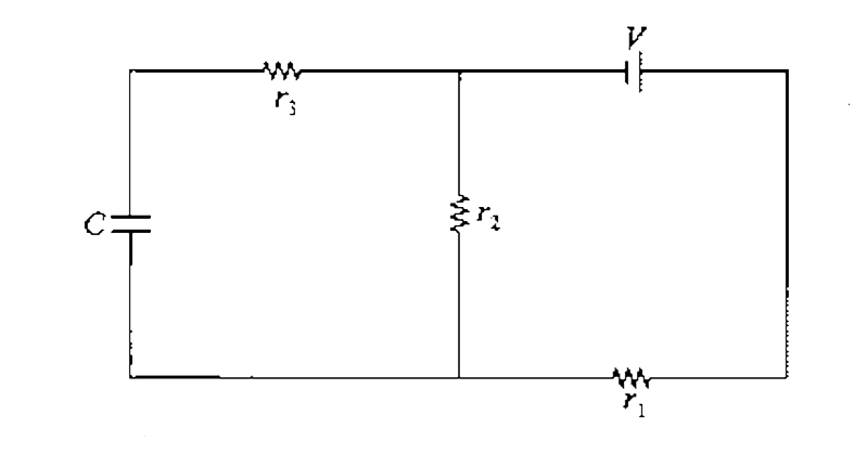
Vr1r1+r2
Vr2r1+r2
V(r1+r2)r2
V(r2+r1)r1+r2+r3
The correct Answer is:B
Step by step video, text & image solution for In the circuit shown in figure, the final voltage drop across the capacitor C is : by Physics experts to help you in doubts & scoring excellent marks in Class 12 exams.
Updated on:21/07/2023Topper's Solved these Questions
- CAPACITANCEBook:PHYSICS GALAXY - ASHISH ARORAChapter:CAPACITANCEExercise:ADVANCE MCQS
Explore 26 Videos
- CAPACITANCEBook:PHYSICS GALAXY - ASHISH ARORAChapter:CAPACITANCEExercise:UNSOLVED NUMERICAL PROBLEMS
Explore 40 Videos
- CAPACITANCEBook:PHYSICS GALAXY - ASHISH ARORAChapter:CAPACITANCEExercise:CONCEPTUAL MCQA
Explore 32 Videos
- ATOMIC PHYSICSBook:PHYSICS GALAXY - ASHISH ARORAChapter:ATOMIC PHYSICSExercise:Unsolved Numerical Problems
Explore 39 Videos
- CURRENT ELECTRICITYBook:PHYSICS GALAXY - ASHISH ARORAChapter:CURRENT ELECTRICITYExercise:All Questions
Explore 389 Videos
Similar Questions
Knowledge Check
In the circuit shown in figure the voltage in L and in C are
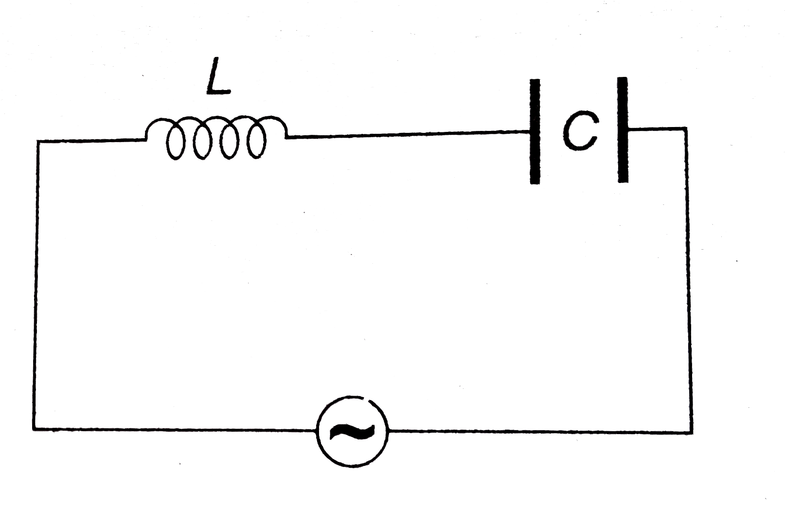 .Ain phaseBout of phase by 90∘Cout of phase by 180∘Din a phase difference which depends upon the values of L C .
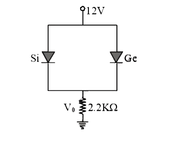
In the circuit shown in figure, Voltage V0 is
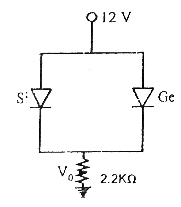 A11.7 voltB11.3 voltC0DNone
In the circuit shown in the figure, the potential difference across the 4.5μF capacitor is
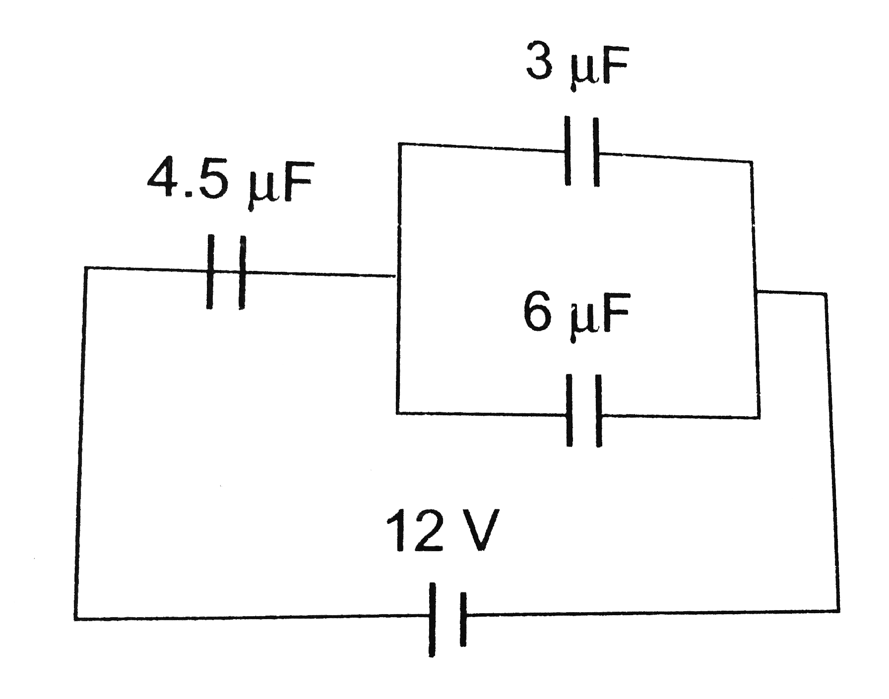 A83voltsB4 voltsC6 voltsD8 volts
In the circuit shown in figure potential difference across
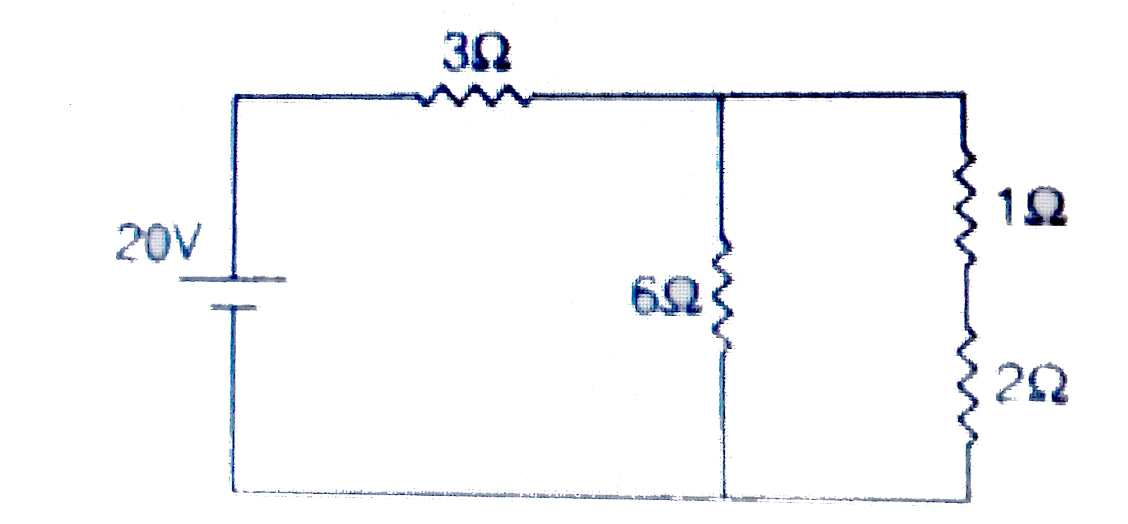
View Solution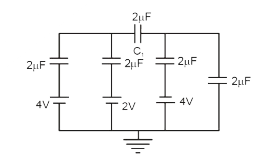
Find voltage across capacitor C1
View SolutionIn a series CR circuit shown in figure,the applied voltage is 10V and the voltage across capacitor is found to be 8V
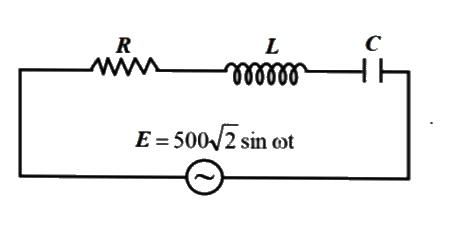
View SolutionIn the series L−C−R circuit shown in the figure, the rms voltage across the resistor and inductor are 400 V and 700 V respectively. If the applied voltage is E=500√2sin(ωt), then the peak voltage across the capacitor is
View Solution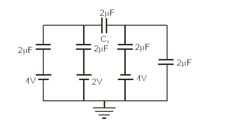 Find voltage across capacitor C1.
View Solution


