In the labortary, the high emf of a battery is measured by using potentiometer and two resistance R1 and R2, where R1<<R2 as shown in the figure
R1=(100±0.10)Ω and R2=(9900±9.90)Ω, AB=1m The voltage across R1, when switches S1 & S2 are connected to point 1 and point 2 is balanced against l1=(60±0.06)cm. when the switches S1 and S2 are shifted to point 3 and point 4 as shown in the figure, the potential difference of standard E0=2 volt is balanced against length l2=(75±0.075)cm. The maximum error in emf of battery E is __________ volts (upto two decimal places)
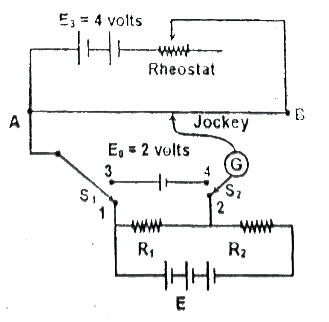
E=2×6075×(10000100)=160 volt , E=E0l1l2(R1+R2R1)
ΔEE=∣∣∣Δl1l1∣∣∣+∣∣∣Δl2l2∣∣∣+∣∣∣Δ(R1+R2)R1+R2∣∣∣+∣∣∣ΔR1R1∣∣∣
⇒ΔE=0.64 volts
Topper's Solved these Questions
- GMP ASSESMENTBook:FIITJEEChapter:GMP ASSESMENTExercise:Objective problems
Explore 215 Videos
- GMP ASSESMENTBook:FIITJEEChapter:GMP ASSESMENTExercise:Assertion & Reason
Explore 15 Videos
- GENERAL PHYSICSBook:FIITJEEChapter:GENERAL PHYSICSExercise:MATRIX MATCH TYPE
Explore 3 Videos
- GRAVITATIONBook:FIITJEEChapter:GRAVITATIONExercise:Numerical based Question
Explore 2 Videos
Similar Questions
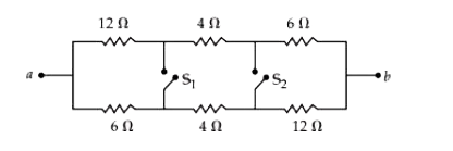
In the given figure switches S1andS2 are in open condition. The resistance across ab when the switches S1andS2 are closed is ……………… Ω.
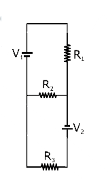
View SolutionTwo ideal batteries of emf V1andV2 and these resistances R1,R2andR3 are connected as shown in the figure . The current in resistance R2 would be zero if
View Solution
Knowledge Check
Given Resistance R1=(8±0.4)Ωand Resistence, R2=(8±0.6)Ω What is the net resistence when R1 and R2 are connected in series?
A(16±0.4Ω)B(3.45±0.3)ΩC(3.45±0.4)ΩD(3.45±0.5)ΩTwo resistors of resistance R1 and R2 having R1>R2 are connected in parallel. For equivalent resistance R, the correct statement is
AR>r1+r2BR>√r1r2Cr1<R<r2DR<r1A capacitor C is connected to a battery circuit having two switches S1 and S2 and resistances R1 and R2. The capacitor will be fully charged when
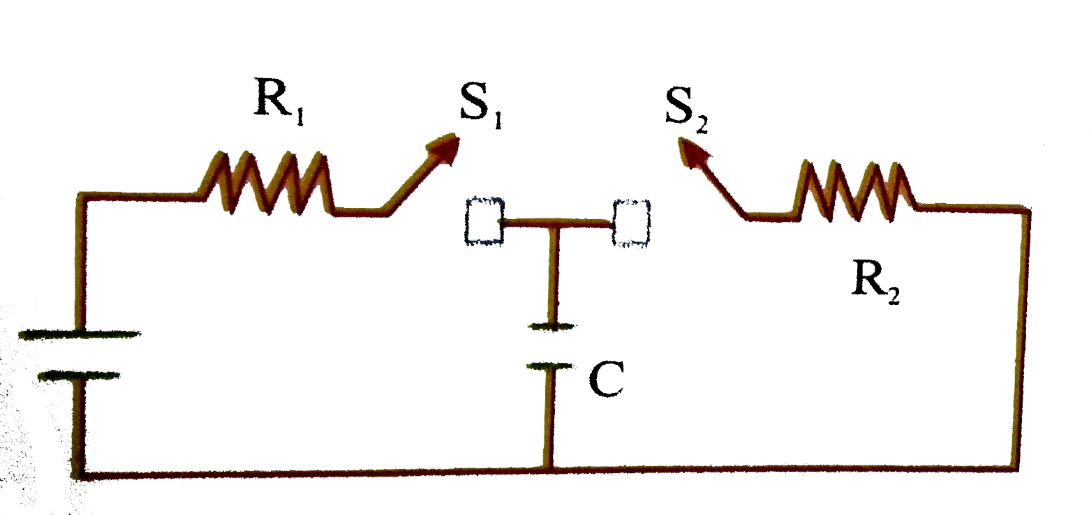 .Aboth S1 and S2 are closedBS1 is closed and S2 is openCS1 is open and S2 is closedDany of the above
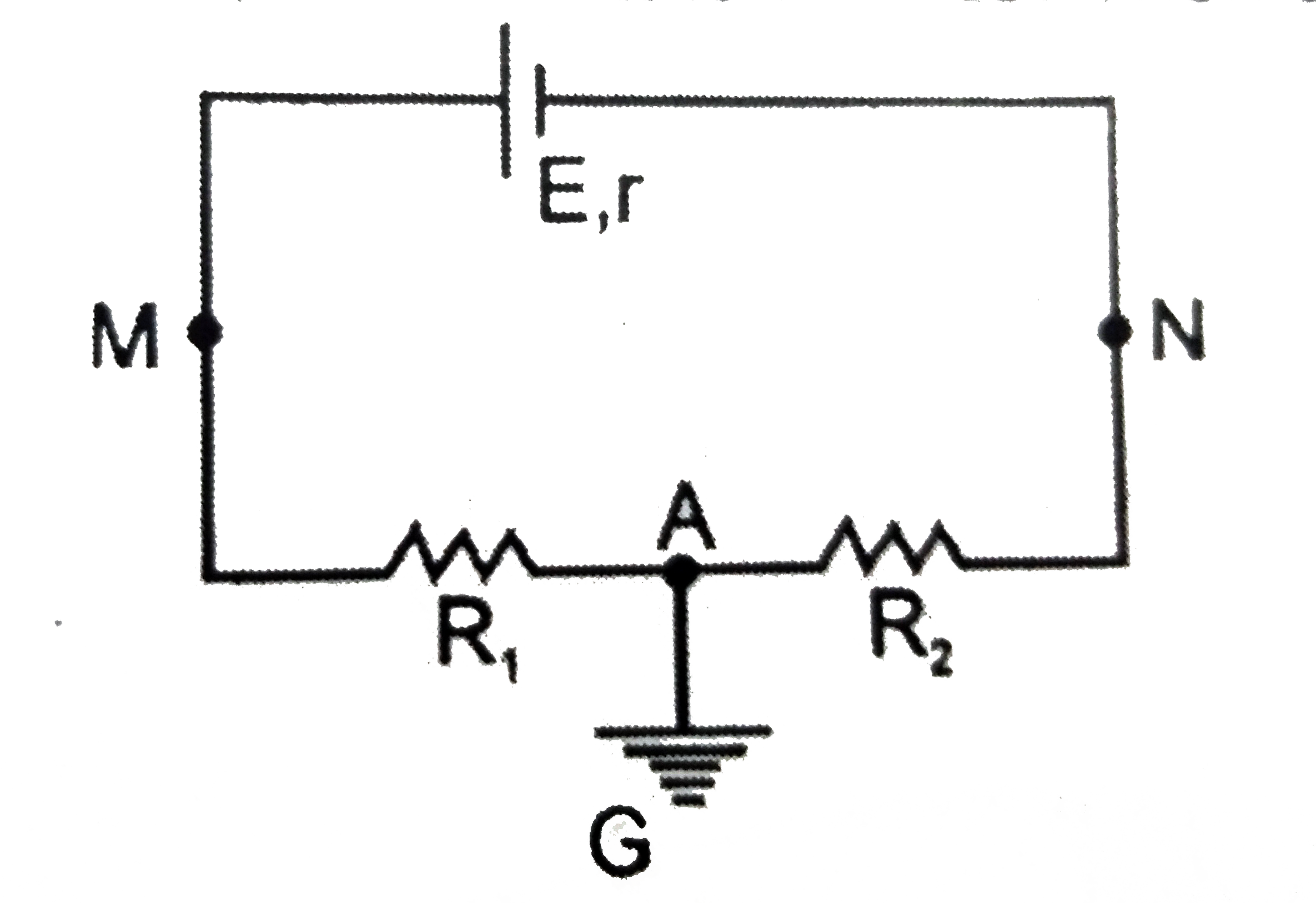
In the given figure, E=12V, R1=3Ω,R2=2Ω and r=1Ω. The choose the correct option/s
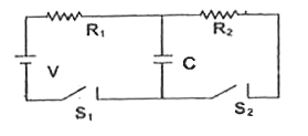
View SolutionA battery of emf V volts, resistances R1 and R2, a condenser C and switches S1, and S2, are connected in a circuit as shown. The capacitor C gets fully charged to V volts when
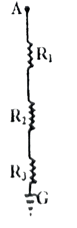
View SolutionA potential of 400V is applied at the point A. The value of resistance R1=1000Ω, R2=2000Ω and R3=1000Ω are connected between points A and G as shown in the figure. Point G is earthed. The measured potential difference by an ideal voltmeter connected across R2 is
View SolutionTo the potentiometer wire of L and 10Ω resistance, a battery of emf 2.5 volts and a resistance R are connected in series. If a potential difference of 1 volt is balanced across L/2 length, the value of R is Ω will be
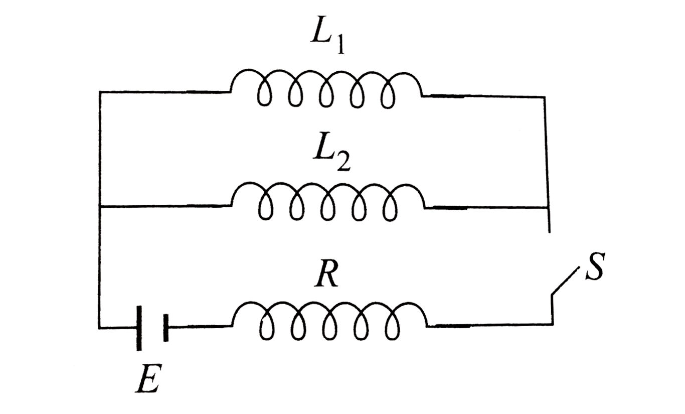
View SolutionIn the circuit, a battery of emf E, a resistance R and inductance coil L1andL2 and switch S are connected as shown. In Fig. Initially the switch is open
View Solution

