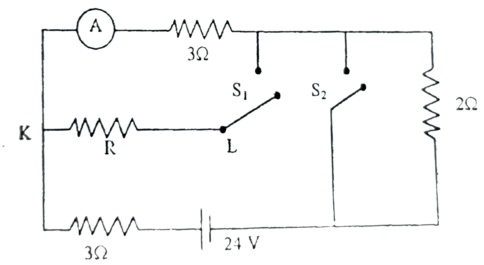
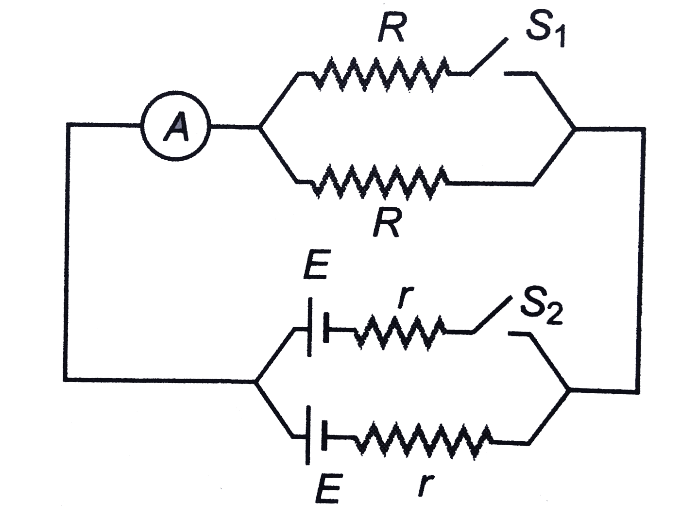
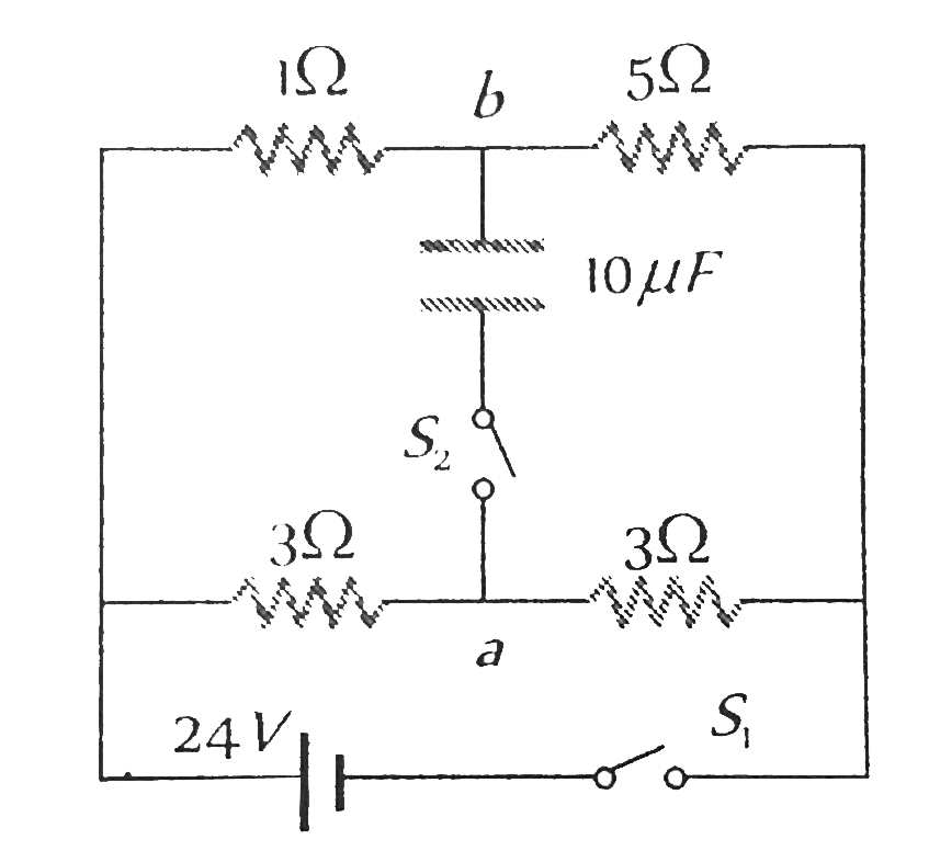
In the circuit shown in the figure, the ideal ammeter reading for current is taken
(a) with both switches open
(b) with both switches closed.
The readings are same in the cases. The value of resistance R is
2Ω
3Ω
4.5Ω
7.5Ω
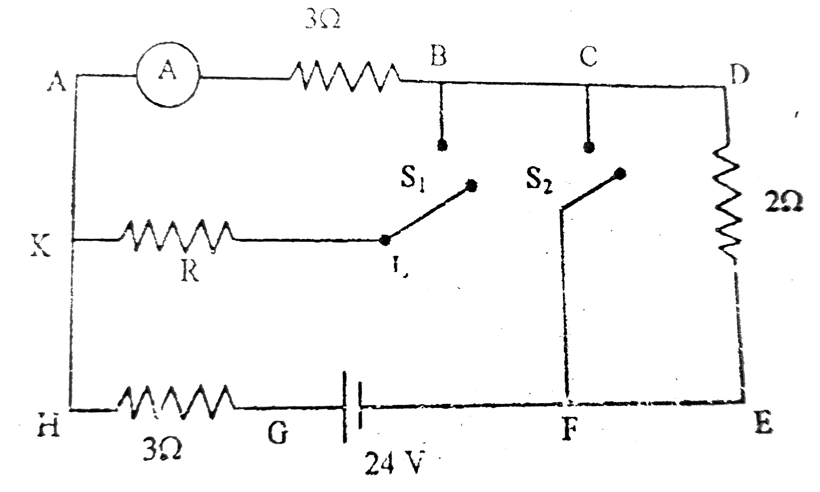
When both switches are open, then reading of ammeter is 24/3=3A
When both switches are closed.
VAB=9V⇒VHG=15⇒ So current through R is 2A.
Hence R=9/2=4.5Ω
Topper's Solved these Questions
- GMP ASSESMENTBook:FIITJEEChapter:GMP ASSESMENTExercise:Assertion & Reason
Explore 15 Videos
- GMP ASSESMENTBook:FIITJEEChapter:GMP ASSESMENTExercise:Multiple Question
Explore 58 Videos
- GMP ASSESMENTBook:FIITJEEChapter:GMP ASSESMENTExercise:Numerical Based
Explore 61 Videos
- GENERAL PHYSICSBook:FIITJEEChapter:GENERAL PHYSICSExercise:MATRIX MATCH TYPE
Explore 3 Videos
- GRAVITATIONBook:FIITJEEChapter:GRAVITATIONExercise:Numerical based Question
Explore 2 Videos
Similar Questions
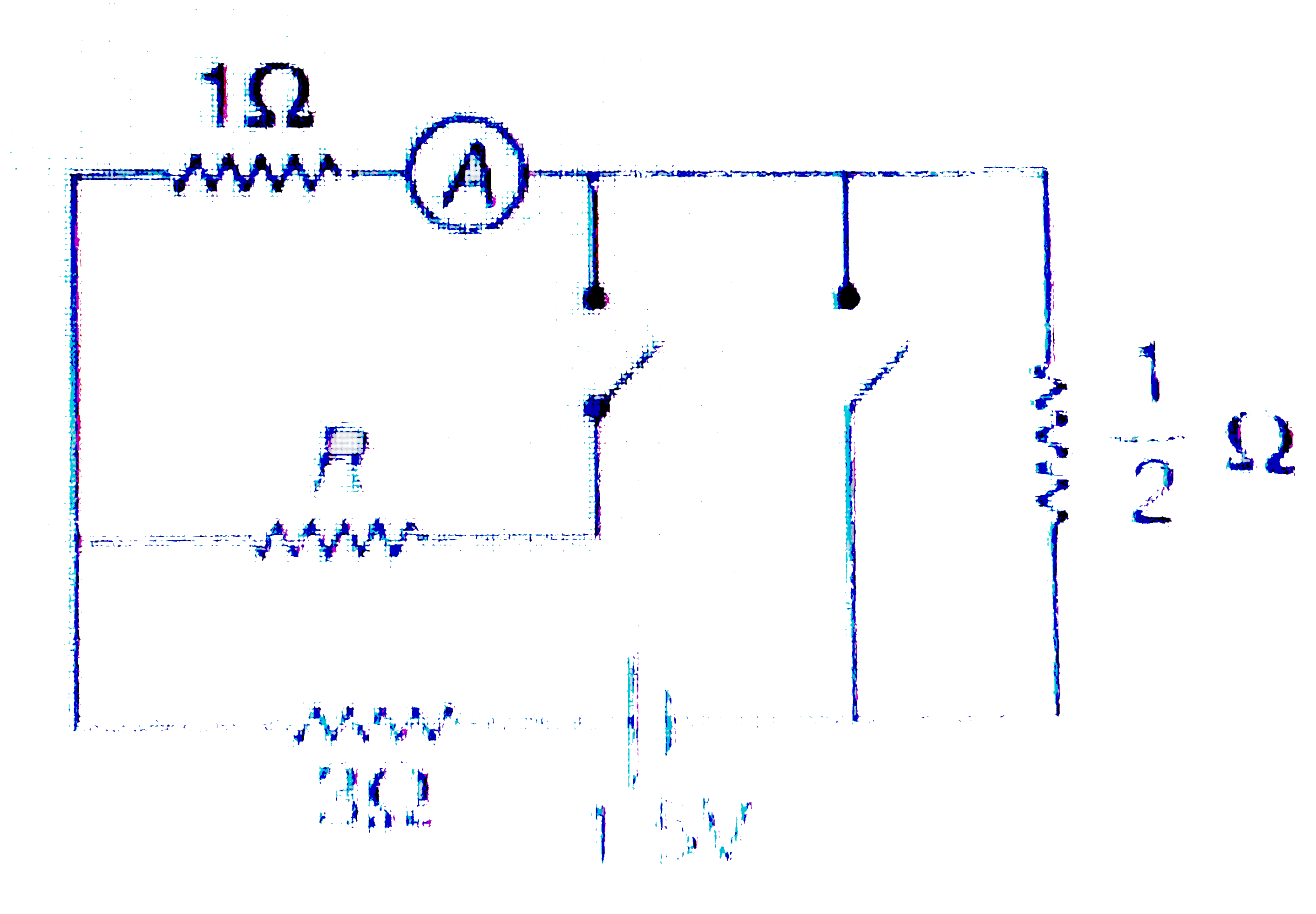
In the circuit as shown in figure , the reading of ammeter (ideal) in the same with both switches one and both switches closed. Find the resistance R ( in Ω)
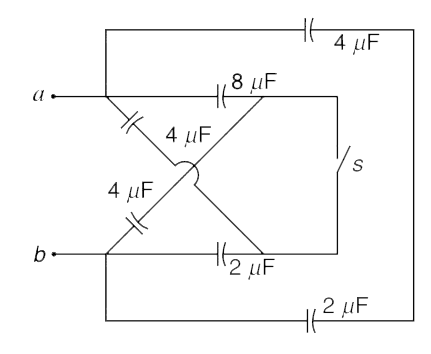
View SolutionIn the circuit shown in the Figure find the equivalent capacitance between points a and b when–
(a) Switch S is open.
(b) Switch S is closed.
View Solution
Knowledge Check
In the circuit shown in figure, reading of ammeter will
 Ashows no deflection if S1 is closedBdecrease if S2 is closedCincrease if S2 is closedDdecrease if S2 is closed
In the circuit shown in figure, what will be the readings of voltmeter and ammeter?
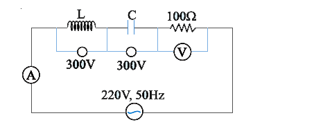 A800 V, 2 AB220 V, 2.2 AC300 V, 2 AD100 V, 2 A
In the circuit shown in figure the reading of ammeter is the same with both switches open as with both closed. Then find the resistance R. (ammeter is ideal).
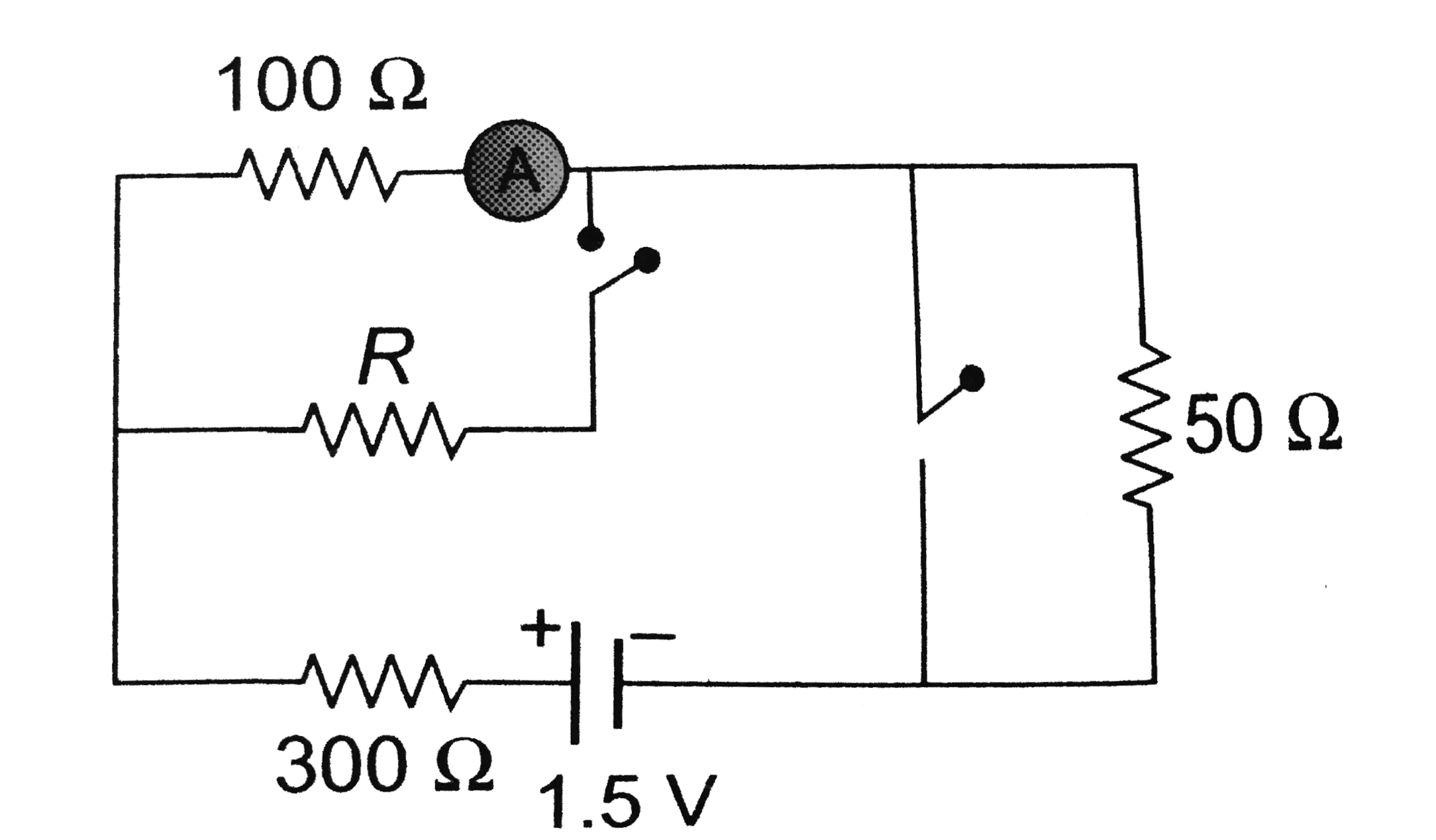 A550ΩB400ΩC350ΩD600Ω
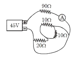
What will the ideal ammeter reading for the circuit shown here ?
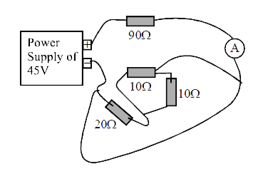
View SolutionWhat will the ideal ammeter read for the circuit shown here?
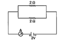
View SolutionIn a circuit shown in figure, the current recorded by an ideal ammeter A is
View SolutionIn the circuit shown, the reading of the ammeter if diode is not ideal, will be

View SolutionIn the circuit shown in figure, switch S is initially closed and S is open. Find V-V
View Solution

